4-4
Chapter 4 Connection to the External Devices Ventilator Measurement and Alarm Input
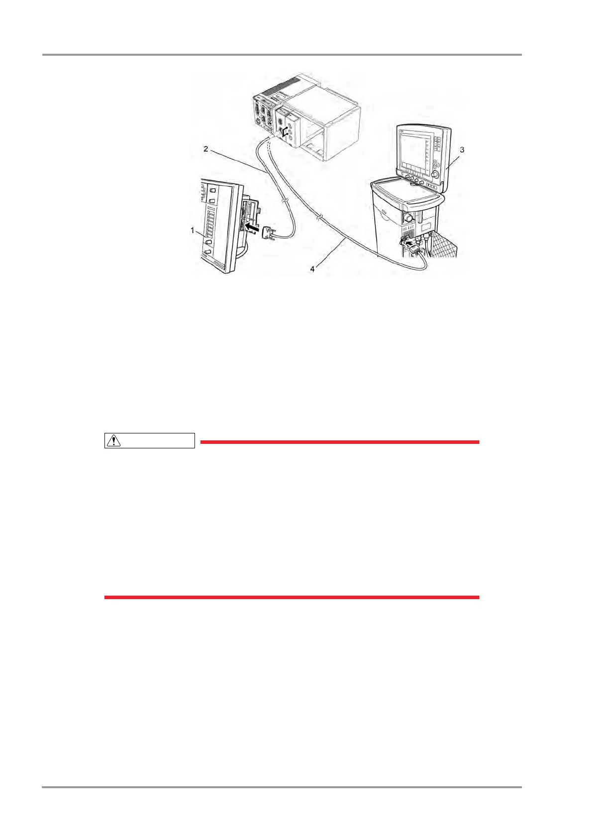
1 SV-300
2 CJ-401RI-70SV3
3 SERVO- i/s
4 CJ-402RI-70SVi
In Case of SERVO-U/SERVO-n/SERVO-air
1Connect the SERVO-U, SERVO-n, SERVO-air to the Status II connector on the DSC-8500, or one of Status
II connector A or Status II connector B on the HP-800.
In Case of VELIA, ASTRAL, VS ULTRA
1Connect the VELIA, ASTRAL, VS ULTRA to the Status II connector on the DSC-8500.
Connection of PB740/760/840
When connecting the PURITAN-BENNETT ventilator, the serial port (RS-232C) of the
ventilator should be set as follows. Refer to the service representative of the ventilator
manufacturer.
Baud Rate: 9600bps
Data Bit: 8bit
Parity Bit: None
(Stop Bit: 1bit)
The DS-8500 system detects the "ventilator alarm" when the nurse call port on the ventilator
outputs the alarm signal.
For details of ventilator setup and alarm signal output condition from the nurse call port, refer
to the service representative of the ventilator manufacturer.
1Connect the PB740/760/840 to STATUS II connector on the DS-8500, or one of STATUS II connector A or
STATUS II connector B on the multiport module.
(The illustration is example of connection with HP-800.)