34. Remove power steering pump assembly.
35. Remove sub frame together with side member.
(a) Remove front engine mounting assembly and rear en-
gine mounting assembly from engine assembly.
(b) Remove sub frame assembly.
36. Remove starter mounting components
[4G18-3708100].
37. Remove transmission assembly.
(a) Fix crankshaft with special tool, ant then remove 6 bolts.
(b) Remove transmission assembly.
38. Remove clutch assembly [4G18-1601000]
and flywheel components [4G18-1005120J].
(a) Fix crankshaft with special tool, ant remove clutch
assembly at first.
(b) Then remove flywheel components.
39. Remove throttlesupporting plate [4G18-1008202].
40. Remove intake manifold assembly [4G18-
1008200].
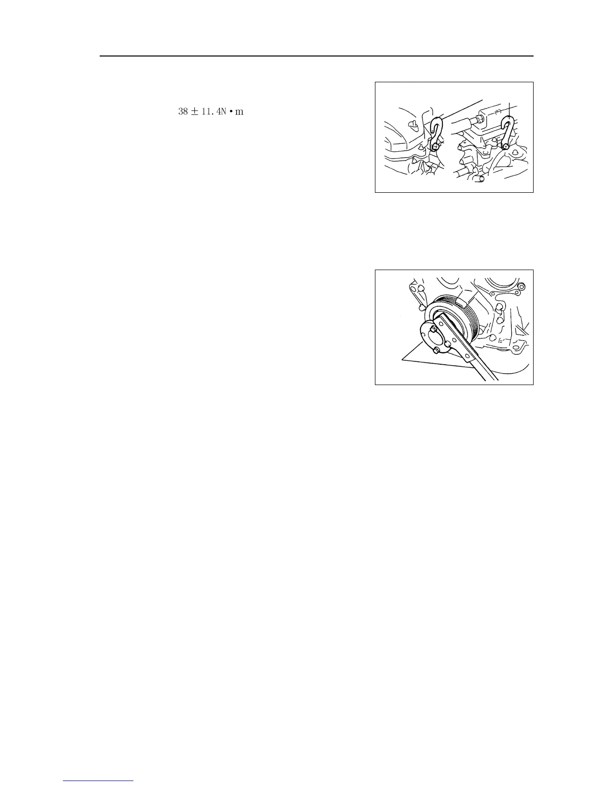
(f) As shown in the diagram, install front and rear hooks of
engine.
Torque:
Hint: install engine hooks to front and rear sides of
engine.
(g)Lift engine assembly with chain pulley block and en-
gine lifting device.
Engine mechanism - Engine assembly
Special tool
39
41. Remove exhaust manifold upper heat shield components [4G18-1008120].
42. Remove exhaust manifold assembly [4G18-1008100].
43. Remove fuel rail injector assembly [4G18-1112100].
44. Remove ignition coil installation components.
45. Remove oil level gauge tube components [4G18-1002140].
46. Remove temperature regulator assembly [4G18-1306100].
47. Disassemble warm air water outlet pipe components [4G18-1300100].
48. Remove oil pressure alerter [4G18-3757100].
Remove oil pressure alerter with SST.
49. Remove the hoses on all hose joint of engine.
Remove clips and hose.
50. Remove drive belt tensioner device.
51. Remove phase sensor [4G18-3600030].
Engine hook
Front
Rear