99
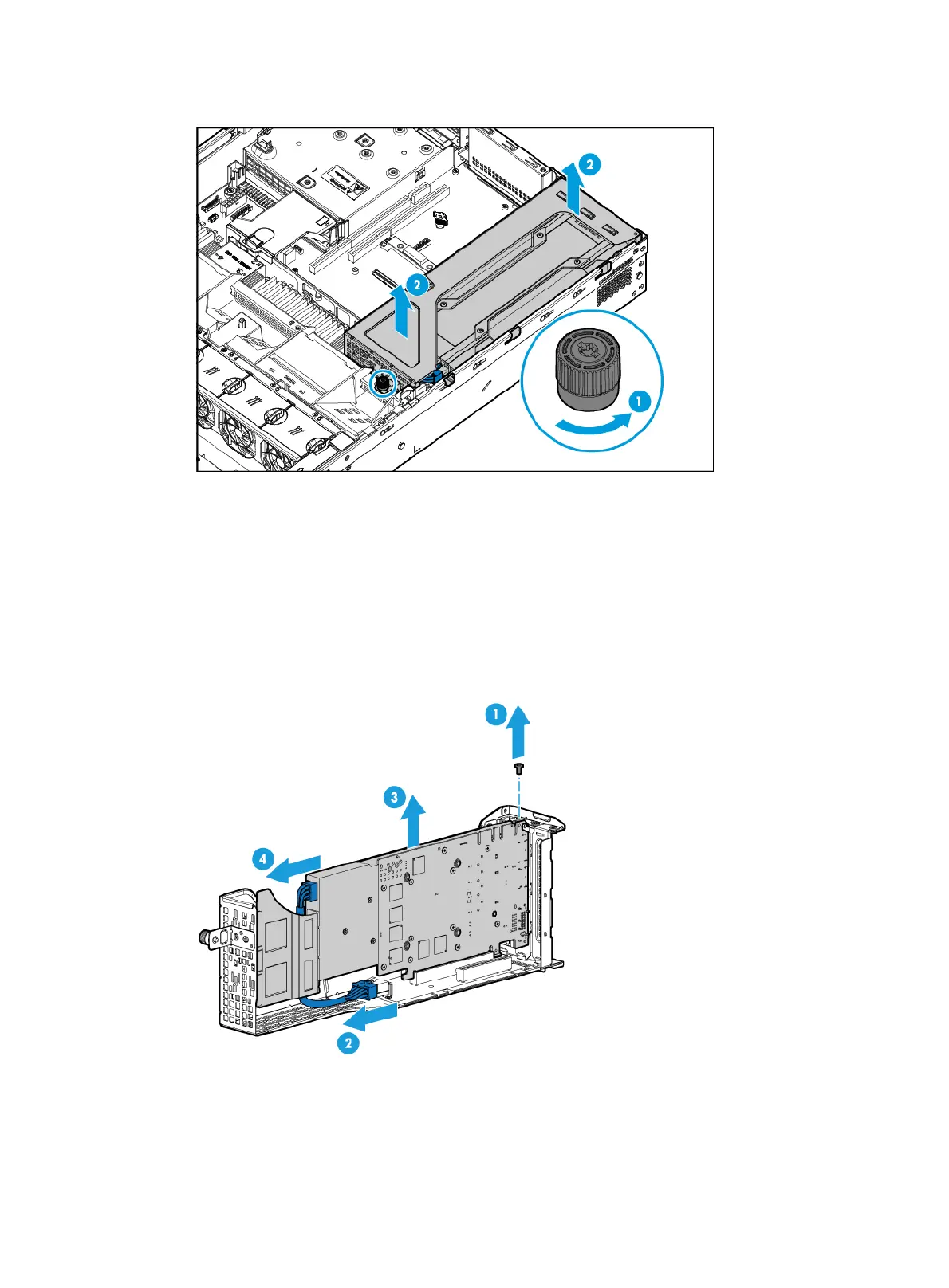
Figure 133 Removing the riser card that has a GPU module attached
5. Remove the GPU module:
a. Remove the screw that secures the GPU module, as shown by callout 1 in Figure 134.
b. Disco
nnect the power cord from the riser card, as shown by callout 2 in Figure 134.
c. Pull the GPU module o
ut of the PCIe slot, and then remove the power cord of the GPU
module (if any), as shown by callouts 3 and 4 in Figure 134.
This exam
ple uses UIS-GPU-M60-1 GPU module in PCIe slot 1 to show the procedure. Not all
GPU modules have power cords.
Figure 134 Removing the GPU module from the riser card
6. Install a new GPU module. For more information, see "Installing GPU modules."
7. Install the access panel. For more information, see "Installing the access panel."
8. Rack-mount the server. For more information, see "Rack-mounting the server."
9. Con
nect the power cord. For more information, see "Connecting the power cord."

 Loading...


