9. Series 8 I/O Link Fiber Optic Extenders (FOE)
9.3. Component mounting sequence
R500 Series 8 I/O User's Guide 247
April 2017 Honeywell
Prerequisite
Before connecting the FOE module's IOL interface cable to the module, refer the FOE
connection rules.
To connect the IOLINK interface cable to the FOE module
Ensure the IOLINK interface cable, IOLink connector and power connector
are properly aligned with the connector on the FOE module.
Press plug firmly into the connector.
Fasten the screws on the cable connector and power connector to the FOE
module.
Connecting the fiber optic cables to the FOE module
ATTENTION
Unused optical ports should always have protective covers on them to
prevent dust and other contaminants from accumulating on the glass fiber
optic interfaces.
Prerequisite
Before connecting the FOE module's power cable to the module, refer the FOE
connection rules.
To connect the FOE cables to the FOE module
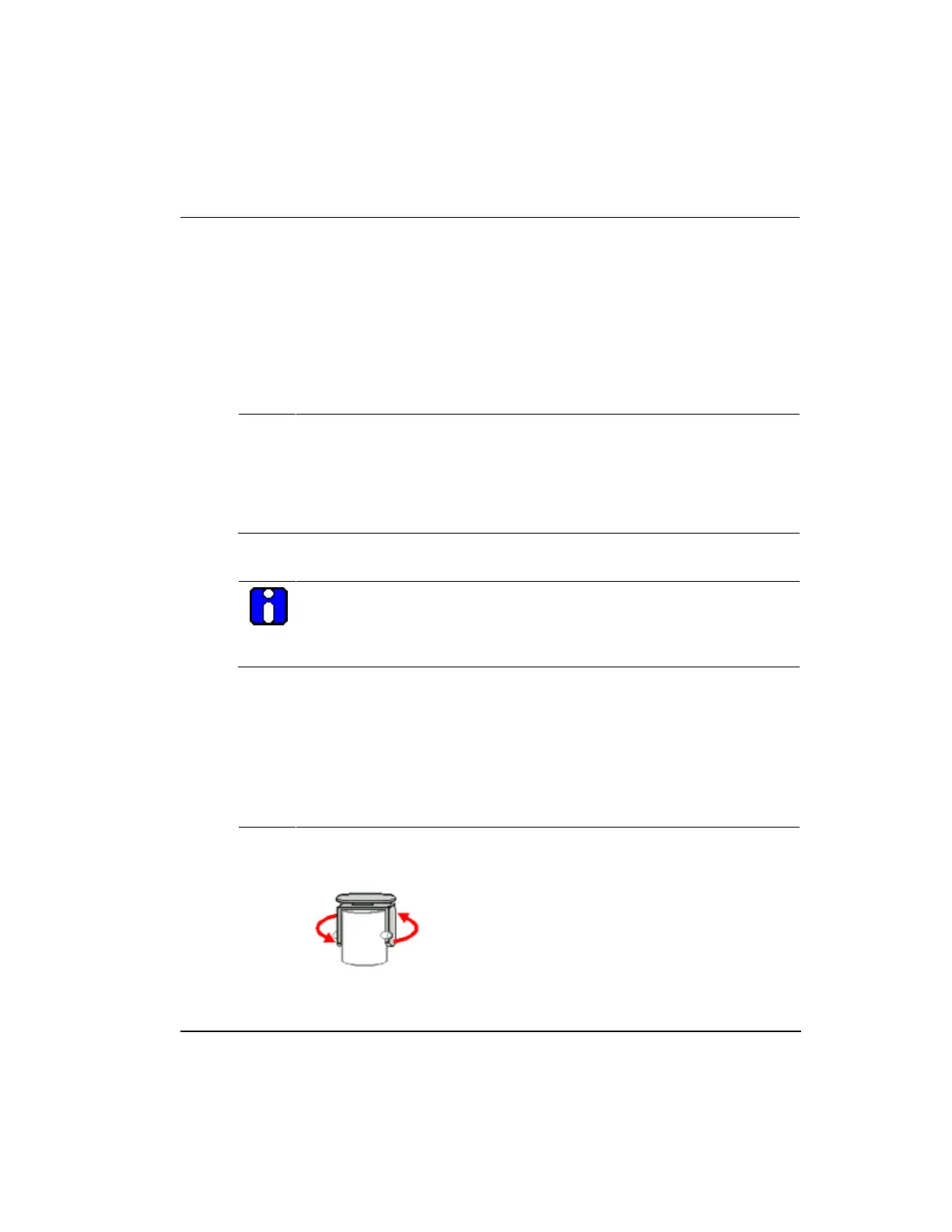
Ensure the terminal caps are removed from the ST optical ports on the FOE
module. If the terminal caps are still attached, rotate the cap counter-
clockwise to disengage the cap from the locking tab.
Insert the ST connector of the fiber optic cable onto the proper FOE port.
Top
 Loading...


