9. Series 8 I/O Link Fiber Optic Extenders (FOE)
9.4. Defining the Fiber Optic topology
R500 Series 8 I/O User's Guide 249
April 2017 Honeywell
The IOLINK cable between the C300 and the FOE module can
be removed or replaced when in power.
Fiber optic cables
under power
Fiber-optic ST-type connectors may be removed, or replaced,
while active.
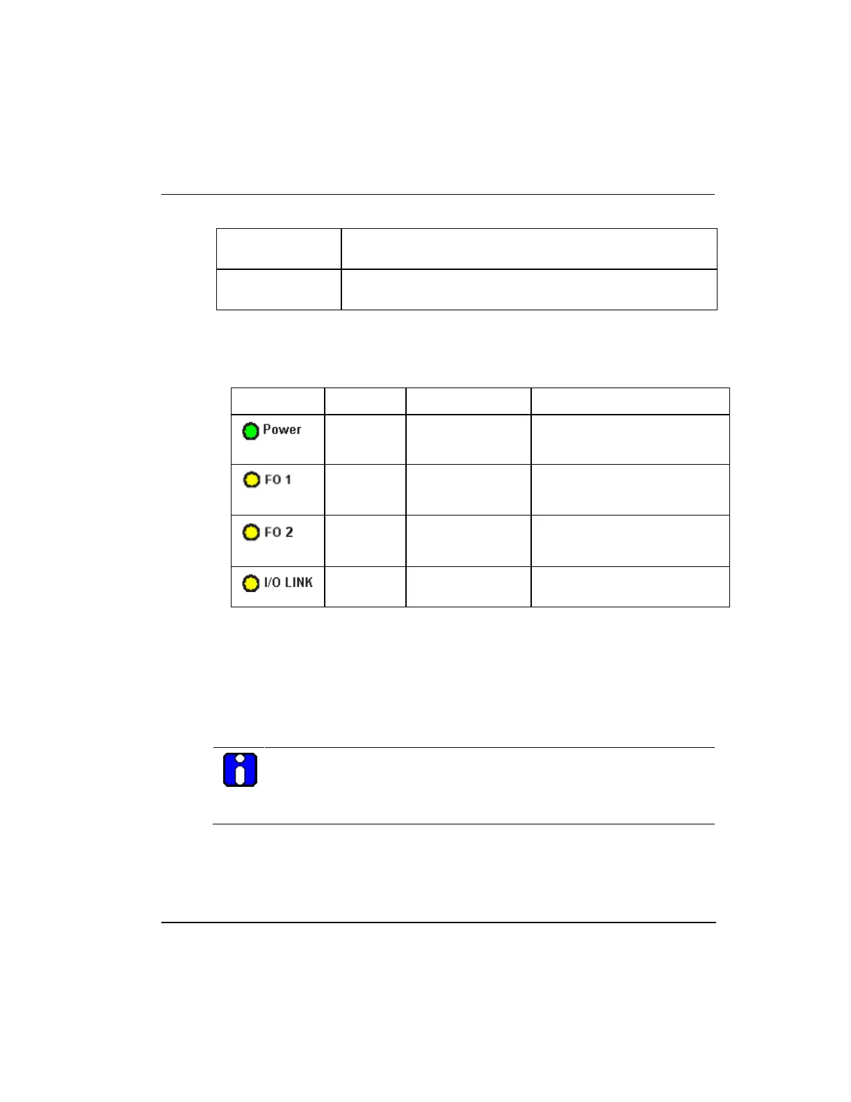
LED indicators
The following table defines the LEDs located on the FOE module.
Table 64 FOE LED descriptions
Communication
signal not present
Communication signal present
on Rx channel.
Communication
signal not present
Communication signal present
on Rx channel.
Communication
signal not present
Communication signal present
on RS485 port.
9.4 Defining the Fiber Optic topology
There are three different FOE topologies supported. These topologies are:
Daisy chain
Tree
Star
ATTENTION
The following figure is an example of how the FOE can be deployed in a
variety of topologies for Series 8 environment. This graphic is not to depict
any restrictions with regards to FOE capacity or cable length.
 Loading...


