Chapter 5
Troubleshooting
System Board Diagnostic LEDs
130
System Board Diagnostic LEDs
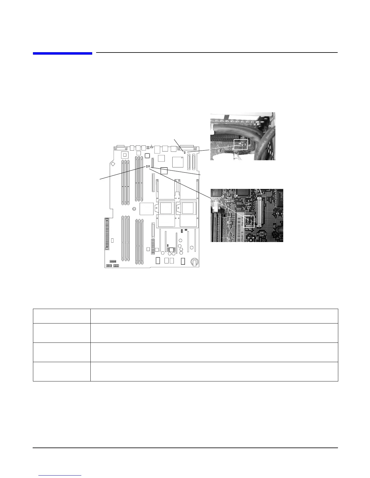
There are three additional LEDs that can help when troubleshooting the server. These LEDs are located on
the system board close to the back of the server and can be viewed through the small cooling holes in the
server case. See Figure 5-3 for the STBY, F/W, and BMC LED locations.
Figure 5-3 Location of the STBY, F/W and BMC LEDs
Table 5-22 details the LED states of the STBY, F/W, and BMC LEDs on the system board.
Table 5-22 System Board LEDs
LED Description
STBY
(power good)
This green standby LED comes on as soon as the server power cord is plugged in.
BMC
(heartbeat)
A few seconds after the server is plugged in this green LED starts blinking indicating
the BMC software is operational.
F/W A few seconds after the server power is turned on, the server firmware code fetch
green LED comes on indicating that the firmware has started the boot process.
system board (enlarged)
System board
STBY
BMC
F/W