Removing and Replacing Components
Removing and Replacing Internal Components
Chapter 4
97
Step 7. If the server has an iLO MP, install it now. See “Replacing iLO MP Hardware” on page 88.
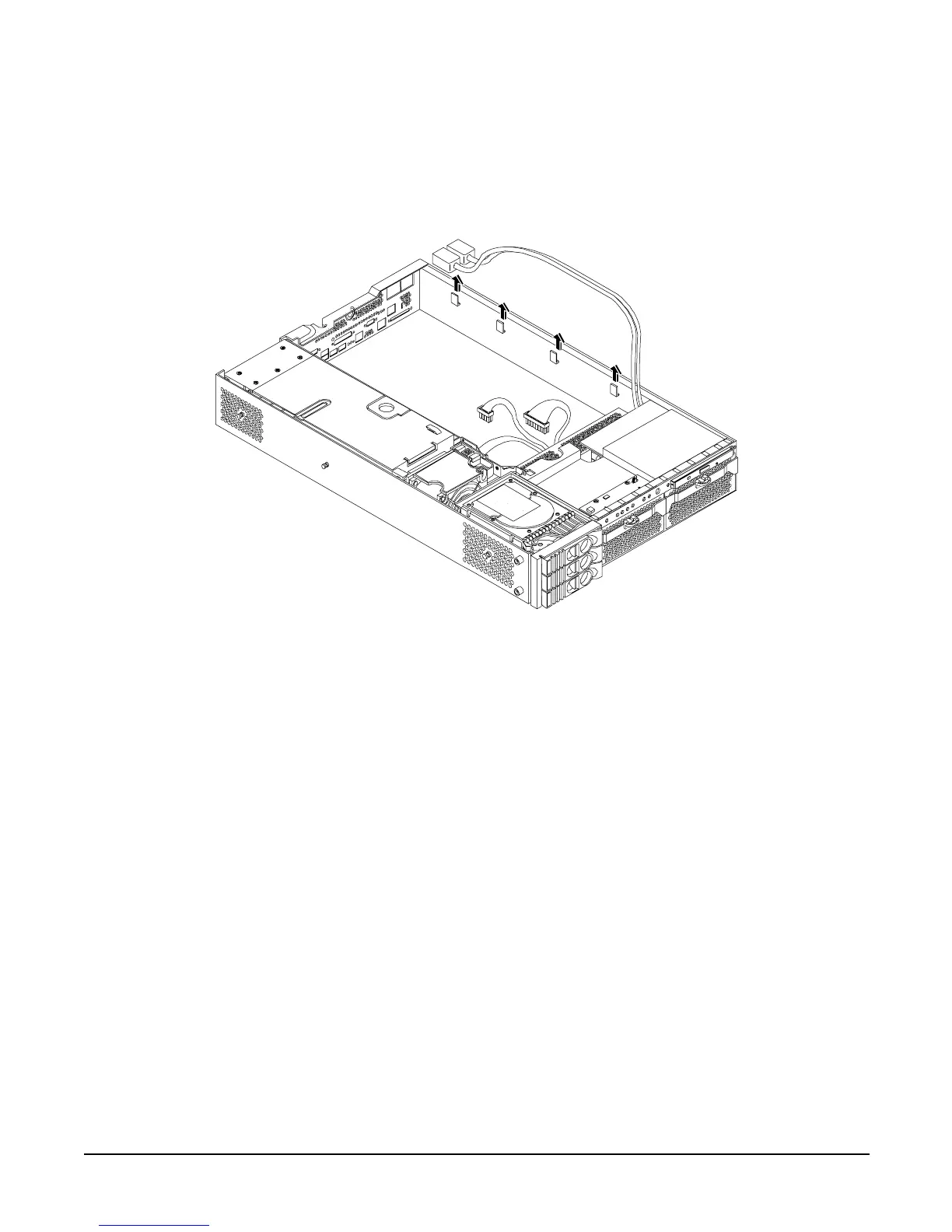
Step 8. Replace the power connectors in their slots on the back of the server and screw in the power
connector mounting screws. See Figure 4-57 for more information.
Figure 4-57 Reinstall the Power Connectors
Step 9. Replace the following server components:
• PCI card cage. See “Replacing the PCI Card Cage” on page 81
• Server fans. See “Replacing a Server Fan” on page 55
• Processors. See “Replacing a Processor” on page 73
• Processor airflow guide. See “Replacing the Processor Airflow Guide” on page 64
• Memory DIMMs. See “Installing DIMMs” on page 67
• Memory airflow guide. See “Replacing the Memory Airflow Guide” on page 62
Step 10. Replace the top metal cover. See “Replacing the Top Metal Cover” on page 51.
Step 11. Reconnect all of the power and external cables.
Step 12. Power on the server. See “Powering On the Server” on page 43.
Step 13. Boot to EFI.
Step 14. Respond YES to prompts regarding copying information onto the new I/O baseboard.
Primary system ID values are are undefined. Do you want to copy the valid system ID values to the
new board? (y/[n])
Y
Step 15. Enter SERVICE mode.
Front of server