Removing and Replacing Components
Removing and Replacing Internal Components
Chapter 4
71
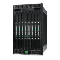
c. At the same time, grasp the back end of the airflow guide and lift the guide out of the server.
Figure 4-27 Removing the Processor Airflow Guide
Step 4. Disconnect the processor power cable from the server power cable.
Step 5. Disconnect the turbo fan power cable from the system board.
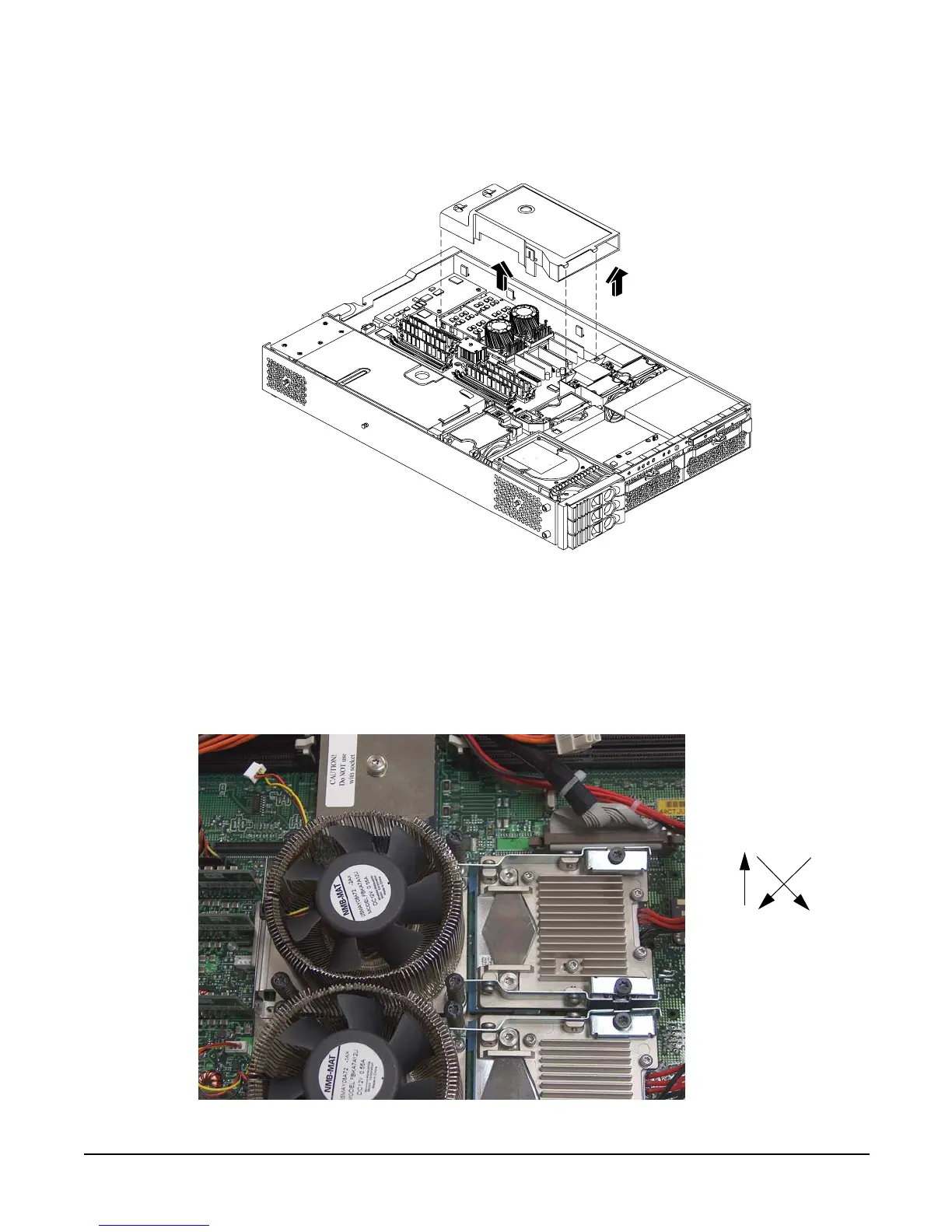
Step 6. Unscrew the two heat sink captive screws, and the four processor captive screws. See Figure 4-28
for the screw locations and removal sequence.
Figure 4-28 Unscrew the Captive Screws
Front of server
Front of server
5
3
Processor
unscrewing pattern
1
2
3
6
4
5
4
6