Removing and Replacing Components
Removing and Replacing Internal Components
Chapter 4
93
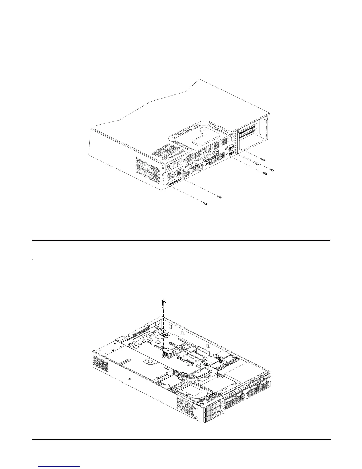
Step 5. Unscrew the six backplane system board mounting screws that connect the system board to the
rear of the server chassis. See Figure 4-50 for more information.
Figure 4-50 Remove System Board Mounting Screws
Step 6. Disconnect all cables that are connected to the system board. To help with re-assembly, make note
of which cables were connected to which port.
NOTE To access the three power cables near the PCI cage, you must lift up the connector
bridge for the PCI cage fan.
Step 7. Unscrew the system board mounting screw. A screw symbol is adjacent to the mounting screw. See
Figure 4-51 for more information.
Figure 4-51 Remove the System Board Mounting Screw
Rear of server
Front of server