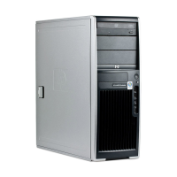
24-pin main power cable connector
112
13 24
1 +3.3V 7 GND 13 +3.3V 19 GND
2 +3.3V 8 POK 14 -12V 20 GND
3 GND 9 +5 Vaux 15 GND 21 +5V
4 +5V 10 +12 V-B 16 PS_ON_L 22 +5V
5 GND 11 +12 V-B 17 GND 23 Unused
6 +5V 12 Unused 18 GND 24 GND
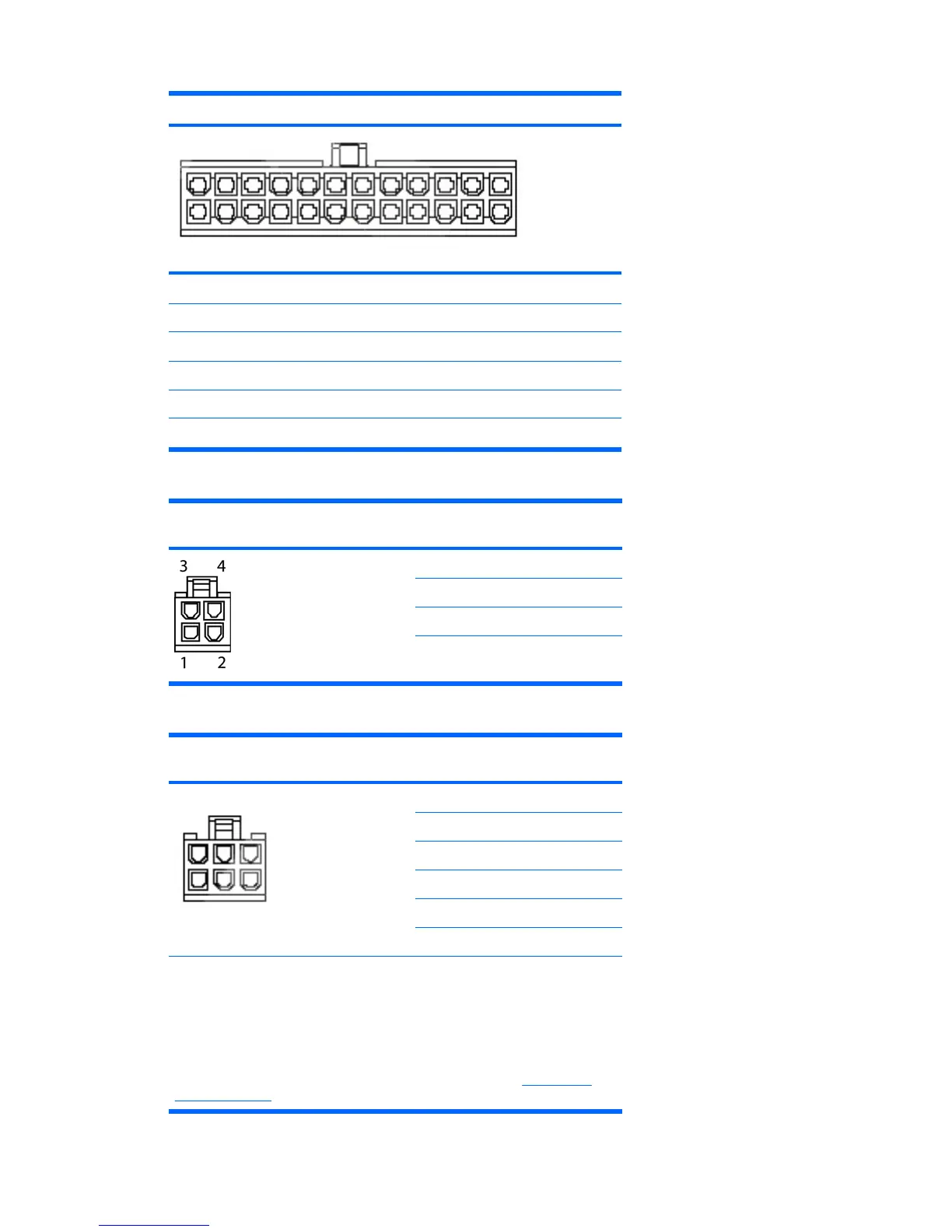
4-pin power (CPU/memory/aux. sys.
board) cable connector
Pin Color Signal
1 BLK GND
2 BLK GND
3 WHT +12 VCPU
4 WHT +12 VCPU
6-pin power (auxiliary PCI Express)
cable connector
Pin Color Signal
46
3
1
1 YEL +12 V-D
2 YEL +12 V-D
3 YEL +12 V-D
4 BLK GND
5 BLK GND
6 BLK GND
CAUTION: Ensure that you can differentiate between which power cable
connects to the PCI Express x16 graphics card and which power cable connects
to the system board. These two cables have different pin counts and different
colors. The PCI Express power cable has a 6-pin black connector, and the system
board power cable has an 4-pin white connector. When power is present, you
must never connect the PCI Express power cable to the system board. If you do
so, the system board can be damaged and your warranty voided. To see a picture
of the PCI Express cable and where it must be connected, see
PCI Express
cards on page 81.
ENWW Connector pin descriptions 159
 Loading...