35
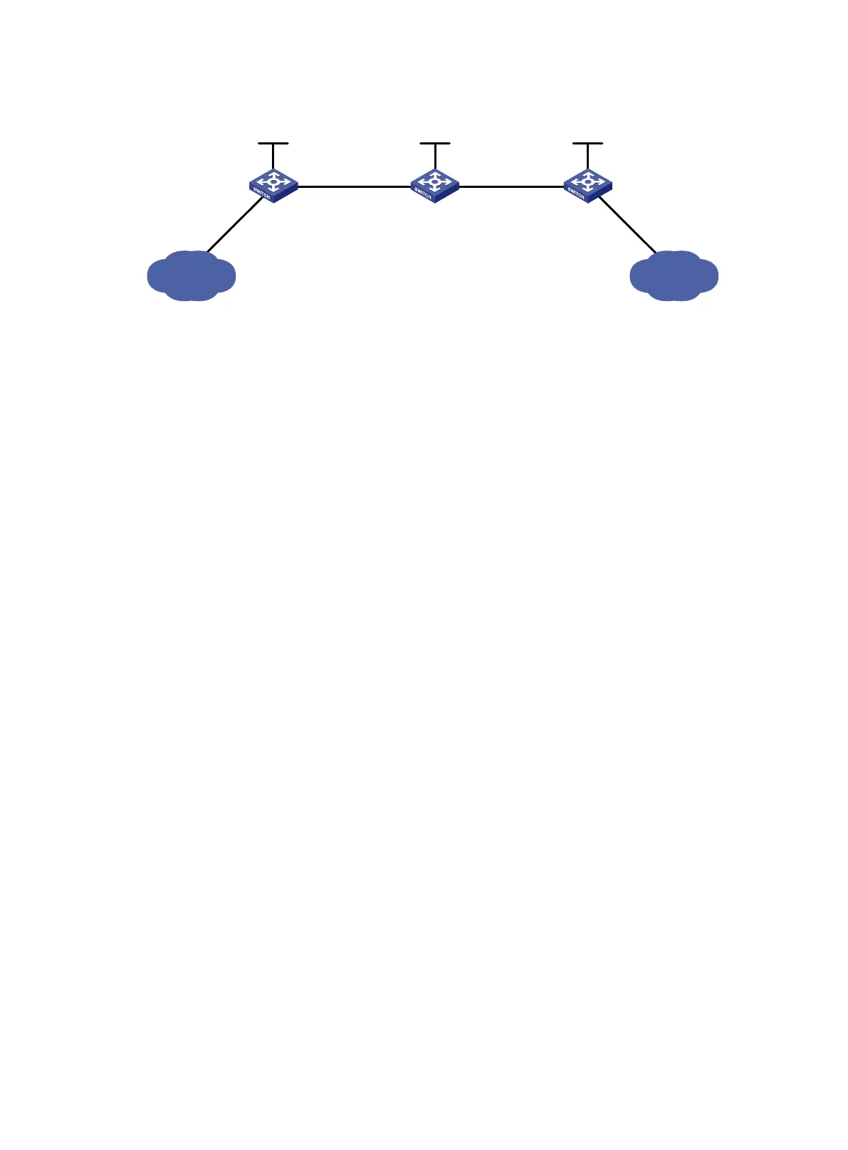
Figure 17 Network diagram
Requirements analysis
• To ensure that the LSRs establish LSPs automatically, enable LDP on each LSR.
• To establish LDP LSPs, configure a routing protocol to ensure IP connectivity between the
LSRs. This example uses OSPF.
• To control the number of LSPs, configure an LSP generation policy on each LSR.
Configuration procedure
1. Configure IP addresses and masks for interfaces, including the loopback interfaces, as shown
in Figure 17. (Details not shown.)
2. Configure OSPF on each switch to ensure IP connectivity between them:
# Configure Switch A.
<SwitchA> system-view
[SwitchA] ospf
[SwitchA-ospf-1] area 0
[SwitchA-ospf-1-area-0.0.0.0] network 1.1.1.9 0.0.0.0
[SwitchA-ospf-1-area-0.0.0.0] network 10.1.1.0 0.0.0.255
[SwitchA-ospf-1-area-0.0.0.0] network 11.1.1.0 0.0.0.255
[SwitchA-ospf-1-area-0.0.0.0] quit
[SwitchA-ospf-1] quit
# Configure Switch B.
<SwitchB> system-view
[SwitchB] ospf
[SwitchB-ospf-1] area 0
[SwitchB-ospf-1-area-0.0.0.0] network 2.2.2.9 0.0.0.0
[SwitchB-ospf-1-area-0.0.0.0] network 10.1.1.0 0.0.0.255
[SwitchB-ospf-1-area-0.0.0.0] network 20.1.1.0 0.0.0.255
[SwitchB-ospf-1-area-0.0.0.0] quit
[SwitchB-ospf-1] quit
# Configure Switch C.
<SwitchC> system-view
[SwitchC] ospf
[SwitchC-ospf-1] area 0
[SwitchC-ospf-1-area-0.0.0.0] network 3.3.3.9 0.0.0.0
[SwitchC-ospf-1-area-0.0.0.0] network 20.1.1.0 0.0.0.255
[SwitchC-ospf-1-area-0.0.0.0] network 21.1.1.0 0.0.0.255
[SwitchC-ospf-1-area-0.0.0.0] quit
Loop0
2.2.2.9/32
Vlan-int3
20.1.1.1/24
Loop0
3.3.3.9/
32
Loop0
1.1.1.9/32
Vlan-int2
10.1.1.1/
24
Vlan-int2
10.1.1.2/24
Vlan-int3
20.1.1.2/24
Switch A Switch B Switch C
11.1.
1
.
0
/
24 21.1.1.0/24
Vlan-int4
11.1.1.1/24
Vlan-int5
21.1.1.1/24

 Loading...