43
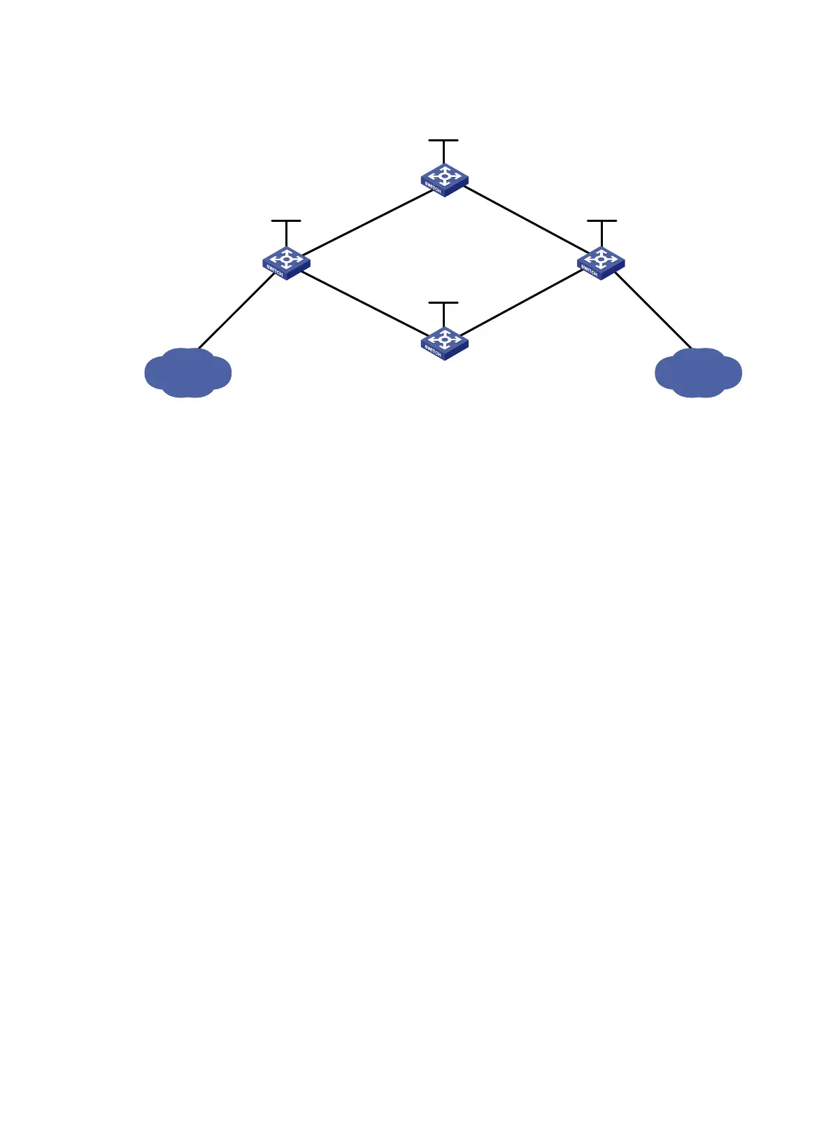
Figure 19 Network diagram
Requirements analysis
• To ensure that the LSRs establish LSPs automatically, enable LDP on each LSR.
• To establish LDP LSPs, configure a routing protocol to ensure IP connectivity between the
LSRs. This example uses OSPF.
• To ensure that LDP establishes LSPs only for the routes 11.1.1.0/24 and 21.1.1.0/24, configure
LSP generation policies on each LSR.
• To ensure that LDP establishes LSPs only over the link Switch A—Switch B—Switch C,
configure label advertisement policies as follows:
Switch A advertises only the label mapping for FEC 11.1.1.0/24 to Switch B.
Switch C advertises only the label mapping for FEC 21.1.1.0/24 to Switch B.
Switch D does not advertise label mapping for FEC 21.1.1.0/24 to Switch A. Switch D does
not advertise label mapping for FEC 11.1.1.0/24 to Switch C.
Configuration procedure
1. Configure IP addresses and masks for interfaces, including the loopback interfaces, as shown
in Figure 19. (Details not shown.)
2. Configure OSPF on each switch to ensure IP connectivity between them. (Details not shown.)
3. Enable MPLS and LDP:
# Configure Switch A.
<SwitchA> system-view
[SwitchA] mpls lsr-id 1.1.1.9
[SwitchA] mpls ldp
[SwitchA-ldp] quit
[SwitchA] interface vlan-interface 2
[SwitchA-Vlan-interface2] mpls enable
[SwitchA-Vlan-interface2] mpls ldp enable
[SwitchA-Vlan-interface2] quit
[SwitchA] interface vlan-interface 6
[SwitchA-Vlan-interface6] mpls enable
[SwitchA-Vlan-interface6] mpls ldp enable
[SwitchA-Vlan-interface6] quit
Switch A
Switch B
Switch C
Loop0
1.1.1.9/32
Loop0
3
.
3.
3
.9
/32
Vlan-
int2
10.1.1.1/24
Vlan-int3
20
.
1
.1.1/24
Vlan-int2
10
.
1.
1.
2
/24
Vlan-int3
20.
1
.1
.2
/
24
11.1.1.0/24
21.1.1.0
/24
Vlan-int4
11.1.1.1/24
Vlan-int5
21
.
1
.1.1/24
Switch D
Loop
0
4.4.4.9/32
Loop0
2.2.2.9/32
Vlan-int6
30.1.1.1/24
Vlan
-
int
7
40.1.1.2/24
Vlan-int6
30.1.1.2/24
Vlan-int
7
40.1.1.1/24

 Loading...