48
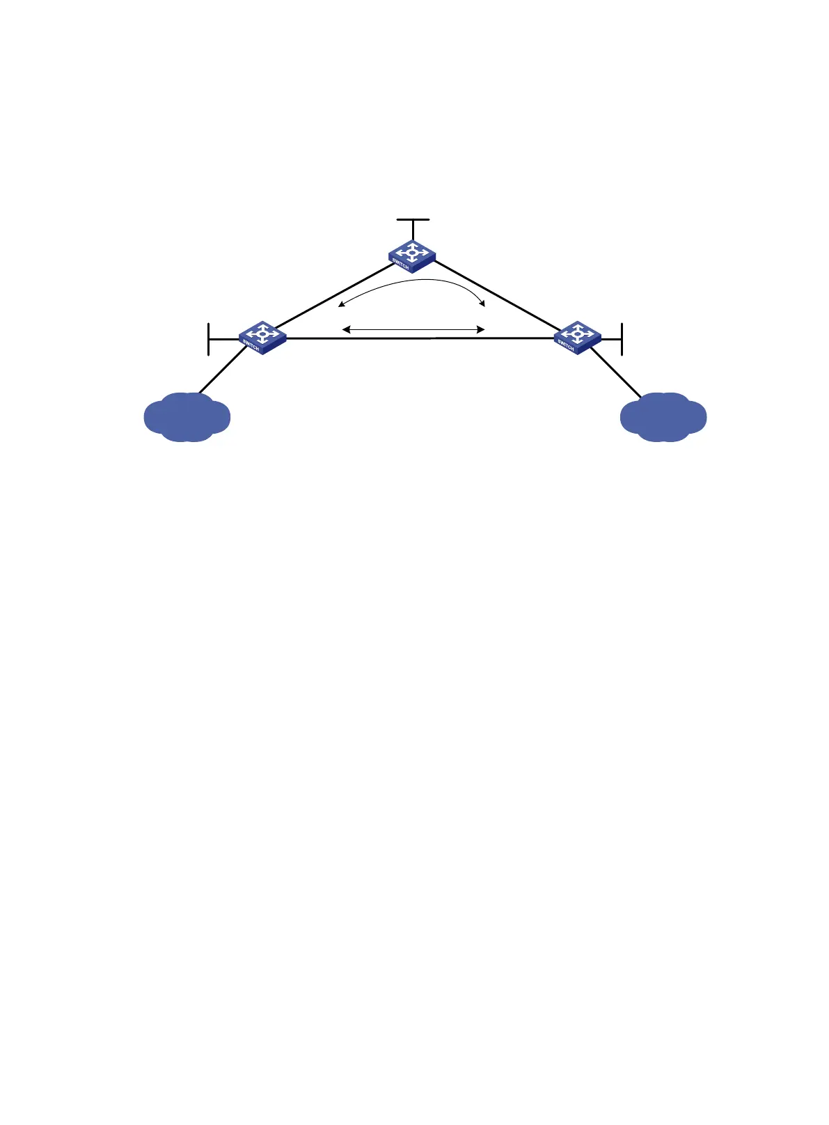
When the primary LSP operates correctly, traffic between subnets 11.1.1.0/24 and 21.1.1.0/24 is
forwarded through the LSP.
When the primary LSP fails, traffic between the two subnets can be immediately switched to the
backup LSP.
Figure 20 Network diagram
Requirements analysis
• To ensure that the LSRs establish LSPs automatically, enable LDP on each LSR.
• To establish LDP LSPs, configure a routing protocol to ensure IP connectivity between the
LSRs. This example uses OSPF.
• To ensure that LDP establishes LSPs only for the routes 11.1.1.0/24 and 21.1.1.0/24, configure
LSP generation policies on each LSR.
• To allow LDP to establish backup LSRs, configure OSPF FRR on Switch S and Switch D.
Configuration procedure
1. Configure IP addresses and masks for interfaces, including the loopback interfaces, as shown
in Figure 20. (Details not shown.)
2. Configure OSPF on each switch to ensure IP connectivity between them. (Details not shown.)
3. Configure OSPF FRR by using one of the following methods:
(Method 1.) Enable OSPF FRR to calculate a backup next hop by using the LFA algorithm:
# Configure Switch S.
<SwitchS> system-view
[SwitchS] bfd echo-source-ip 10.10.10.10
[SwitchS] ospf 1
[SwitchS-ospf-1] fast-reroute lfa
[SwitchS-ospf-1] quit
# Configure Switch D.
<SwitchD> system-view
[SwitchD] bfd echo-source-ip 11.11.11.11
[SwitchD] ospf 1
[SwitchD-ospf-1] fast-reroute lfa
[SwitchD-ospf-1] quit
(Method 2.) Enable OSPF FRR to specify a backup next hop by using a routing policy:
# Configure Switch S.
Loop0
1.1.1.1/32
Switch A
Switch S
Switch D
Vlan-int12
12.12.12.1/24
Vlan-int13
13.13.13.1/24
Vlan-int13
13.13.13.2/24
Vlan-int12
12.12.12.2/24
Vlan-int24
24.24.24.2/24
Vlan-int24
24.24.24.4/24
Loop0
3.3.3.3/32
Primary LSP
Backup LSP
Loop0
2.2.2.2/32
11.1.1.0/24
21.1.1.0/24
 Loading...


