58
How DS-TE operates
A device takes the following steps to establish an MPLS TE tunnel for a CT:
1. Determines the CT.
A device classifies traffic according to your configuration:
When configuring a dynamic MPLS TE tunnel, you can use the mpls te bandwidth
command on the tunnel interface to specify a CT for the traffic to be forwarded by the tunnel.
When configuring a static MPLS TE tunnel, you can use the bandwidth keyword to specify
a CT for the traffic to be forwarded along the tunnel.
2. Checks whether bandwidth is enough for the CT.
You can use the mpls te max-reservable-bandwidth command on an interface to configure
the bandwidth constraints of the interface. The device determines whether the bandwidth is
enough to establish an MPLS TE tunnel for the CT.
The relation between BCs and CTs varies with different BC models:
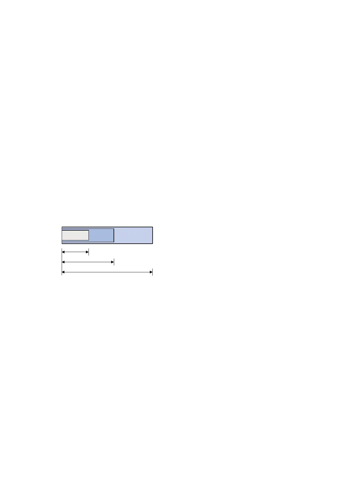
In RDM model, a BC constrains the total bandwidth of multiple CTs, as shown in Figure 25:
• BC 2 is for CT 2. The total bandwidth for CT 2 cannot exceed BC 2.
• BC 1 is for CT 2 and CT 1. The total bandwidth for CT 2 and CT 1 cannot exceed BC 1.
• BC 0 is for CT 2, CT 1, and CT 0. The total bandwidth for CT 2, CT 1, and CT 0 cannot exceed
BC 0. In this model, BC 0 equals the maximum reservable bandwidth of the link.
In cooperation with priority preemption, the RDM model can also implement bandwidth isolation
between CTs. RDM is suitable for networks where traffic is unstable and traffic bursts might occur.
Figure 25 RDM bandwidth constraints model
In MAM model, a BC constrains the bandwidth for only one CT. This ensures bandwidth isolation
among CTs no matter whether preemption is used or not. Compared with RDM, MAM is easier to
configure. MAM is suitable for networks where traffic of each CT is stable and no traffic bursts occur.
Figure 26 shows an example:
• BC 0 is for CT 0. The bandwidth occupied by the traffic of CT 0 cannot exceed BC 0.
• BC 1 is for CT 1. The bandwidth occupied by the traffic of CT 1 cannot exceed BC 1.
• BC 2 is for CT 2. The bandwidth occupied by the traffic of CT 2 cannot exceed BC 2.
• The total bandwidth occupied by CT 0, CT 1, and CT 2 cannot exceed the maximum reservable
bandwidth.
CT 2
CT 2+CT
1 CT 2
+CT 1+CT 0
BC 2
BC 1
BC 0=Max reservable BW
 Loading...


