3.11.5.1 Main Control Module
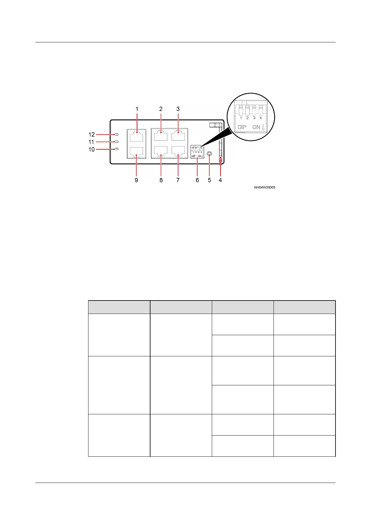
Figure 3-52 Main Control Module
(1) FE_1 (active port) (2) CAN_IN (input port of the
teamwork CAN and
northbound RS485 port)
(3) RS485/12 V (T/H module
port)
(4) Main control module
handle
(5) SW (reserved) (6) DIP switch
(7) COM (northbound RS485
port)
(8) CAN_OUT (output port of
the teamwork CAN and
northbound RS485 port)
(9) FE_2 (standby port)
(10) Alarm indicator (11) Run indicator (12) Power indicator
Table 3-14 Indicator description
Name
Color Status Description
Power indicator Green Steady on The power input
is normal.
O There is no power
input.
Run indicator Green Blinking The device is in
the state of
startup.
O The device is in
the state of
shutdown.
Alarm indicator Red Steady on A failure alarm is
generated.
O No alarm is
generated.
NetCol5000-A025 In-row Air Cooled Smart Cooling
Product
User Manual (300 mm Width) 3 Installation Guide
Issue 15 (2020-12-10) Copyright © Huawei Technologies Co., Ltd. 84