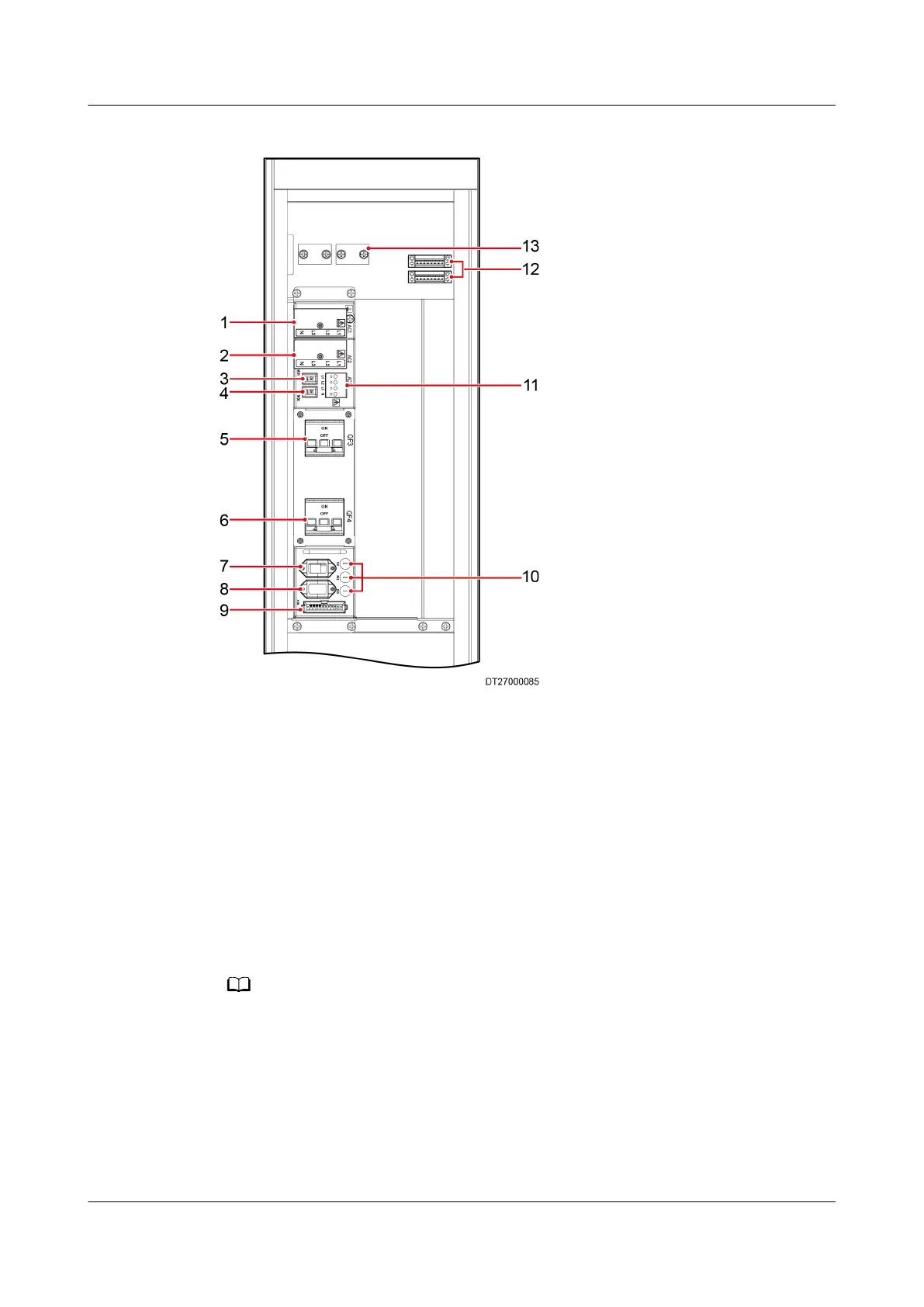
Figure 3-44 Port layout on the electrical control box
(1) Active power supply (AC1) (2) Standby power supply
(AC2)
(3) Contactor control switch
(MD1)
(4) Contactor control switch
(MD2)
(5) Outdoor unit and
compressor switch (QF3)
(6) Heater and humidier
switch (QF4)
(7) Compressor, PSU power
port (X101) (connection not
required onsite)
(8) Electric heating and
humidication power port
(X102) (connection not
required onsite)
(9) External signal port (X103)
(connection not required
onsite)
(10) Fuse (FU1 oil heating belt
fuse, FU2/FU3 contactor coil
fuse)
a
(11) Outdoor unit power (AC3) (12) External signal port (X301,
X302) (connected by yourself)
(13) Cable clip
a: For some models, the oil heating belt fuse and contactor coil fuse are inside the electric
control box.
3.11.2 Connecting the Indoor Unit Power Cable
Prerequisites
Before connecting cables, remove the top cover from the power terminals.
NetCol5000-A025 In-row Air Cooled Smart Cooling
Product
User Manual (300 mm Width) 3 Installation Guide
Issue 15 (2020-12-10) Copyright © Huawei Technologies Co., Ltd. 74