12. Coordinate System Data Editing of the SCARA Axis
: 1 axis – 4 axis of the X-SEL-KX and PX/QX controller
183
168
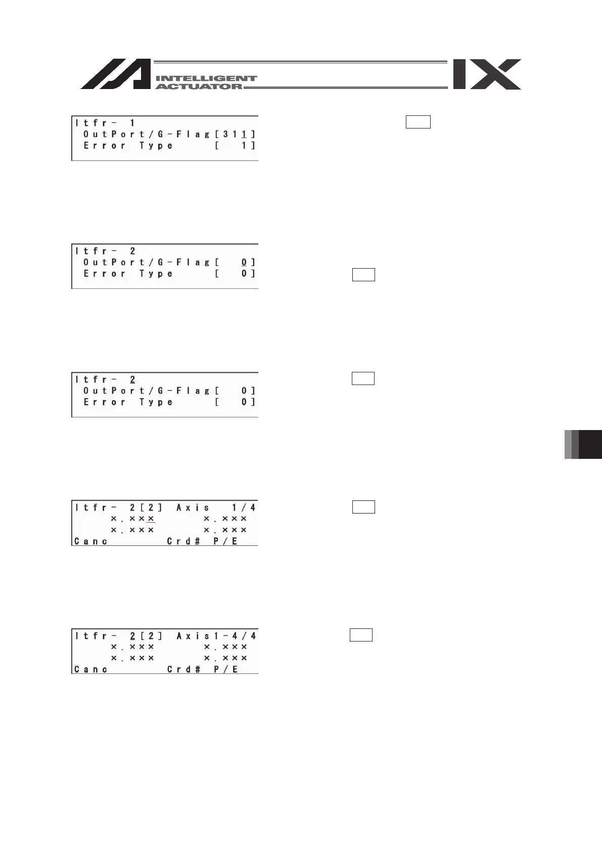
Transfer the data with the WRT key.
The screen advances to the edit screen for the
simple interference check zone No. 2.
When the axial pattern of Ⓐ does not agree with
that of Ⓖ, the “9FO” error occurs.
When the axial pattern of Ⓐ and Ⓖ is 0, the “9F1”
error occurs if the output port or error type is
specified.
Complete editing of the tool coordinate system data
and write the data in Flash ROM.
Pressing the ESC key moves the cursor to the
location of the simple interference check zone No.
Pressing the ESC key returns the cursor to the
coordinate value input screen.
Pressing the ESC key moves the cursor to the
location of the tool coordinate system No.
Pressing the ESC key again returns to the Flash
ROM writing screen.
(Return by 4 screens)
 Loading...


