Be sure to press the EMERGENCY STOP switch before setting an adjusting jig.
Failure to do so may cause a robot malfunction, which may lead to a serious accident
resulting in injury or death.
Warning
!
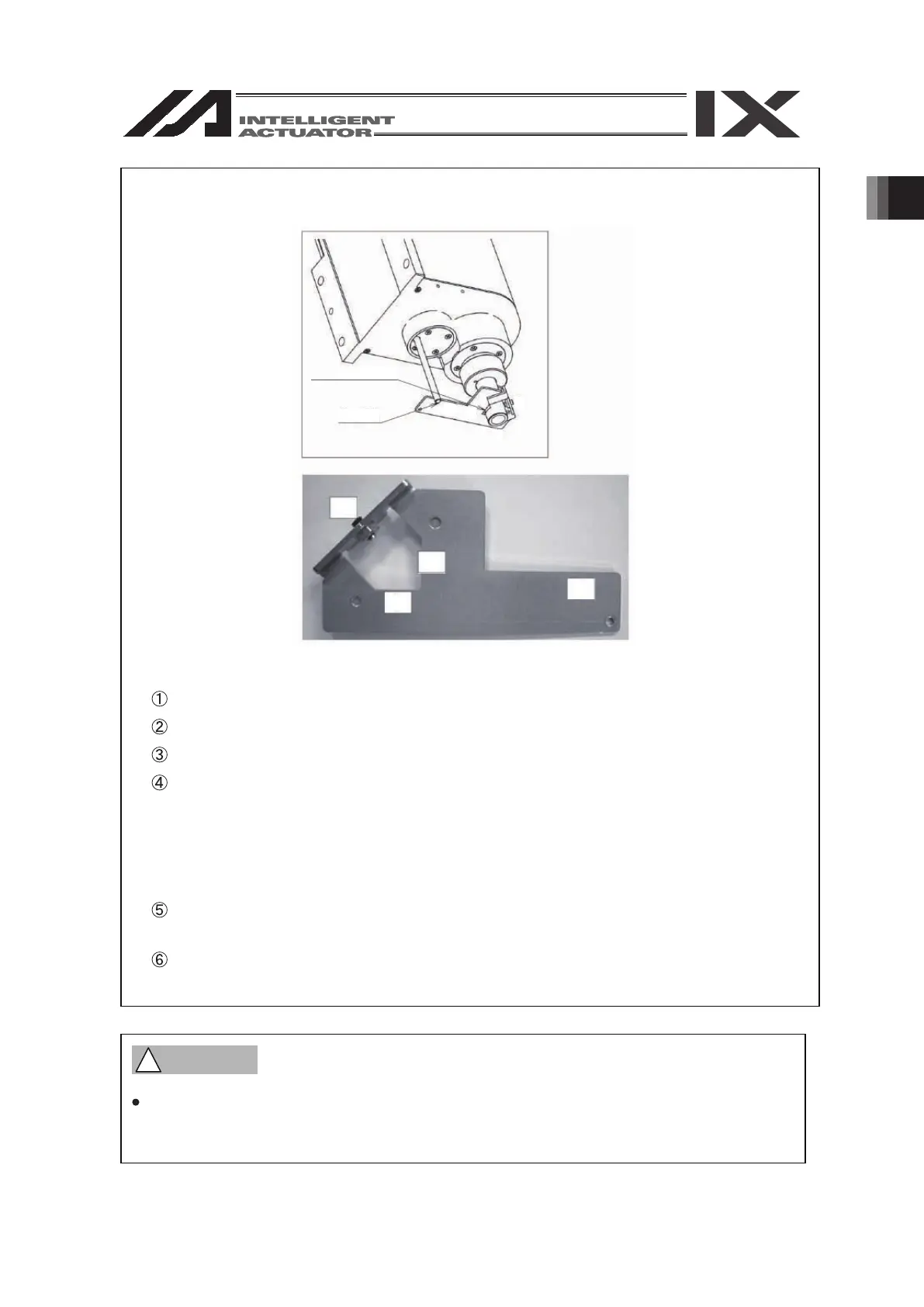
Jig Attachment Procedure
D-shaped surface
Shaft
c
b
d
a
a
d
b
c
Insert the ball screw spline shaft into the jig hole from the lower side.
Put the D-cut surface of the ball screw spline shaft onto the surface “a”.
Put the ball screw spline shaft side surface onto the surface “b”.
Fasten the screw “c” and fix the jig onto the ball screw spline shaft.
Insert the attached shaft into the hole on the ZR unit body.
Turn the ball screw spline shaft and put the attached shaft onto the surface “d” of the jig.
* At that time, make sure that the adjusting jig is placed vertically to the ball screw
* Screws to be used : Hexagon socket head set screw M5
* Tightening Torque : 20 [N▪cm] (reference)
* Be careful because the shaft comes off easily when your hand is released.
spline shaft and the D-cut surface closely contacts the surface “a”.
 Loading...


