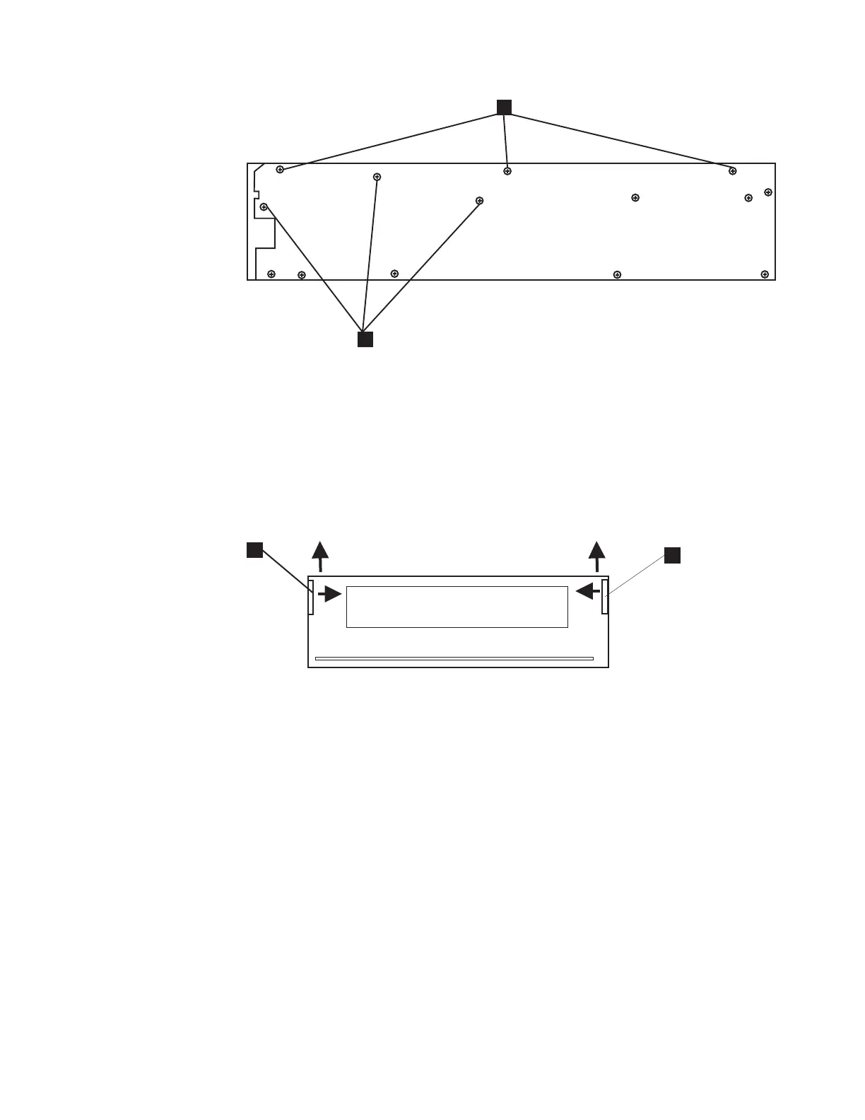
5. Remove the five screws (two on the left side, 2 in Figure 113 on page 180
and three on the right side 2 in Figure 114) that secure the cartridge carrier
to the drive chassis.
6. Locate the white, plastic side rails on either side of the internal drive
mechanism (1 in Figure 115, as viewed from the front of the drive.) Gently
push the side rails toward the center of the drive to release them from their
locating holes and then lift the side rails, along with the cartridge carrier.
7. Slide the cartridge carrier out the front of the drive mechanism.
Note: Use caution when pulling the cartridge carrier away from the drive.
The tape may be wrapped around the rollers. Carefully free the tape
from the drive, lift the door on the tape cartridge, and then wind the
tape back into the cartridge.
8. Remove the cartridge from the cartridge carrier.
9. Reassemble the drive in reverse order.
10. Replace the drive and media and return the failed drive.
1
2
RLHSV527-0
Figure 114. Removing the Right Side Screws
1
1
RLHSV528-0
Figure 115. Removing the Right Side Screws
Chapter 11. Installation and Removal Procedures 181

 Loading...