IMBA-8650 Motherboard
Page 82
CN Type: Dual USB port
CN Location: See
Figure 4-21
CN Pinouts:
See
Figure 4-24 and Table 4-24
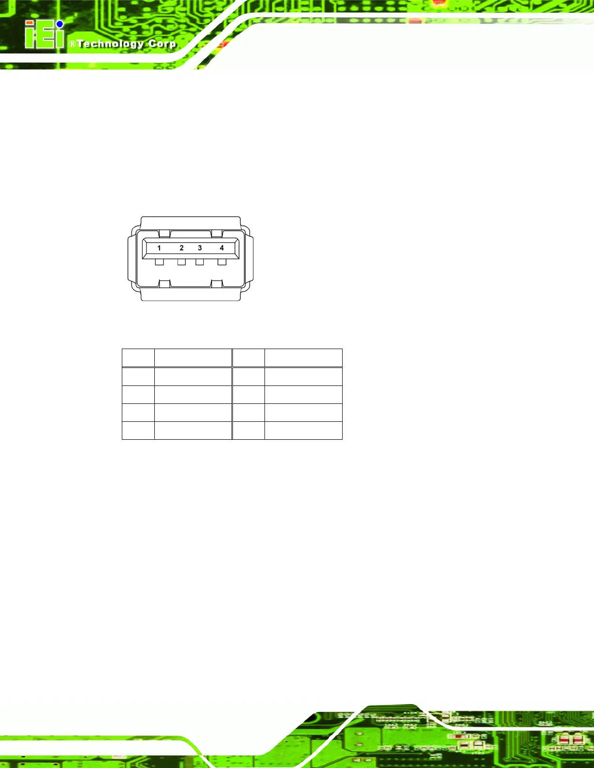
USB devices connect directly to the USB connectors on the external peripheral connector
panel.
Figure 4-24: USB Connector Pinout Locations
PIN DESCRIPTION PIN DESCRIPTION
1 VCC 5 VCC
2 USBD0- 6 USBD0-
3 USBD0+ 7 USBD0+
4 GND 8 GND
Table 4-24: USB Connector Pinouts
4.3.4 Ethernet Connector
CN Label: LAN/USB1
CN Type: RJ-45 ports
CN Location: See
Figure 4-21
CN Pinouts:
See
Figure 4-25, Table 4-25 and Table 4-26
A 1Gb connection can be made between the Ethernet connectors and a Local Area
Network (LAN) through a network hub.
 Loading...


