Home
IEI Technology
Motherboard
IMBA-8650
IEI Technology IMBA-8650 User Manual
5
of 1
of 1 rating
248 pages
Give review
Manual
Specs
To Next Page
To Next Page
To Previous Page
To Previous Page
Loading...
IMBA-8650 Motherboard
Page 186
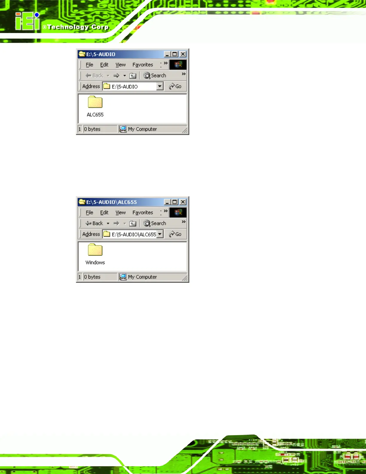
Figure 7-40: Open the ALC655 Folder
Step 3:
Double-click the
ALC665
folder
.
Step 4:
A
new window opens (
Figure
7-41).
Figure 7-41: Open the Windo
ws Folder
Step 5:
Double-click the
Windows
folder
.
Step 6:
A
new window opens (
Figure 7-42
).
205
207
Table of Contents
Table of Contents
7
Default Chapter
6
Packing List
6
1 Introduction
21
Imba-8650 Introduction
22
Imba-8650 Benefits
22
Figure 1-1: IMBA-8650
22
Imba-8650 Features
23
Imba-8650 Overview
23
Figure 1-2: IMBA-8650 Overview
24
Imba-8650 Peripheral Connectors and Jumpers
25
Technical Specifications
26
Table 1-1: Technical Specifications
27
This Page Is Intentionally Left Blank
28
2 Detailed Specifications
29
Overview
30
Dimensions
30
Board Dimensions
30
Figure 2-1: IMBA-8650 Dimensions (MM)
30
External Interface Panel Dimensions
31
Figure 2-2: External Interface Panel Dimensions (MM)
31
Data Flow
32
Figure 2-3: Data Flow Block Diagram
32
Compatible Processors
33
CPU Overview
33
Intel® 865G Northbridge Chipset
33
Intel® 865G Overview
33
Figure 2-5: Intel® 865G Northbridge
34
Figure 2-6: 184-Pin DIMM Sockets
36
Intel® 865G Memory Support
36
Figure 2-7: Integrated Graphics
37
Intel® 865G Integrated Graphics
37
Intel ® Ich5 Southbridge Chipset
40
Intel ® ICH5 Overview
40
Figure 2-8: Intel® ICH5 Southbridge
40
Figure 2-9: Onboard Audio
41
Intel ® ICH5 Audio Codec '97 Controller
41
Intel ® ICH5 IDE Interface
41
Figure 2-10: IDE Interface
42
Intel ® ICH5 Low Pin Count (LPC) Interface
42
Table 2-1: Supported HDD Specifications
42
Figure 2-11: LPC Interface
43
Figure 2-12: PCI Interface
43
Intel ® ICH5 PCI Interface
43
Intel ® ICH5 Real Time Clock
44
Intel ® ICH5 SATA Controller
44
Intel ® ICH5 USB Controller
45
Pci Bus Components
46
PCI Bus Overview
46
Intel® 82541PI PCI Gigabit Ethernet Controller
46
Realtek Gbe Controller
46
Figure 2-15: Gigabit Ethernet
47
Figure 2-16: PCI-To-ISA Bridge
48
ITE IT8888F PCI-To-ISA Bridge Chipset
48
Lpc Bus Components
49
LPC Bus Overview
49
BIOS Chipset
49
Figure 2-17: LPC Bus
49
Figure 2-18: BIOS
50
Super I/O Chipset
50
Figure 2-19: Super I/O
51
Super I/O LPC Interface
52
Super I/O 16C550 Uarts
52
Super I/O Hardware Monitor
53
Super I/O Fan Speed Controller
53
Figure 2-20: Super I/O Serial Ports
53
Super I/O Parallel Port
54
Super I/O Infrared
54
Figure 2-21: Super I/O Parallel Port
54
Super I/O Floppy Disk Drive (FDD) Controller
55
Figure 2-22: Super I/O Infrared Port
55
Super I/O Keyboard and Mouse Controller
56
Figure 2-23: Super I/O Floppy Disk Drive Controller
56
Figure 2-24: Super I/O Keyboard and Mouse Controller
57
Figure 2-25: Fintek Serial Port Chipset
57
Fintek F81216DG LPC Serial Port Chipset
57
Environmental and Power Specifications
58
System Monitoring
58
Operating Temperature and Temperature Control
59
Power Consumption
59
Table 2-2: Power Consumption
59
3 Unpacking
61
Anti-Static Precautions
62
Unpacking
62
Unpacking Precautions
62
Unpacking Checklist
63
Package Contents
63
Table 3-1: Package List Contents
64
Optional Components
65
Table 3-2: Optional Components
66
4 Connector Pinouts
67
Peripheral Interface Connectors
68
IMBA-8650 Layout
68
Figure 4-1: Connector and Jumper Locations
68
External Peripheral Interface Panel Connectors
70
Internal Peripheral Connectors
70
Table 4-1: Peripheral Interface Connectors
70
Table 4-2: External Peripheral Interface Panel Connectors
70
ATX Power Supply Connector (4-Pins)
71
AGP Connector (66-Pins)
71
Figure 4-2: ATX Power Supply Connector (4-Pins) Location
71
Table 4-3: ATX Power Supply Connector (4-Pins) Pinouts
71
Figure 4-3: AGP Slot Location
73
ATX Power Supply Connector (20-Pins)
75
Figure 4-4: ATX Power Connector Location
75
Table 4-4: AGP Slot Pinouts
75
Audio Connector (7-Pin)
76
Figure 4-5: Audio Connector Location (7-Pin)
76
Table 4-5: ATX Power Connector Pinouts
76
Auxiliary Audio Connector (4-Pin)
77
Figure 4-6: Auxiliary Audio Connector Location (4-Pin)
77
Table 4-6: Audio Connector Pinouts (8-Pin)
77
CD-In Connector
78
Figure 4-7: CD-In Connector
78
Table 4-7: Auxiliary Audio Connector Pinouts (4-Pin)
78
Compact Flash Socket
79
Table 4-8: CD-In Connector
79
Figure 4-8: CF Card Socket Location
80
Fan Connectors
81
Table 4-9: CF Card Socket Pinouts
81
Figure 4-9: Fan Connectors Locations
82
Floppy Disk Connector
82
Table 4-10: Fan Connectors Pinouts
82
Figure 4-10: FDC Connector Location
83
Figure 4-11: Front Panel Connector Pinout Locations
84
Front Panel Connector (12-Pin)
84
Table 4-11: FDC Connector Pinouts
84
Figure 4-12: IDE Device Connector Locations
85
IDE Connector (40-Pin)
85
Table 4-12: Front Panel Connector Pinouts
85
ISA Slot
86
Table 4-13: IDE Connector Pinouts
86
Figure 4-13: ISA Slot Location
87
Infrared Interface Connector (5-Pin)
89
Table 4-14: PCI Slot
89
Figure 4-14: Infrared Connector Pinout Locations
90
PCI Slot
90
Table 4-15: Infrared Connector Pinouts
90
Figure 4-15: PCI Slot Location
91
Table 4-16: PCI Slot
93
Figure 4-16: SATA Drive Connector Locations
94
SATA Drive Connectors
94
Figure 4-17: Serial Port Connector Pinout Locations
95
Serial Port Connector (RS-232/422/485)
95
Table 4-17: SATA Drive Connector Pinouts
95
Figure 4-18: Serial Port Connector (RS-422/485) Pinout Locations
96
Serial Port Connector (RS-422/485)
96
Table 4-18: Serial Port Connector Pinouts
96
Figure 4-19: SPDIF Connector Pinout Locations
97
SPDIF Connector
97
Table 4-19: Serial Port Connector (RS-422/485) Pinouts
97
Figure 4-20: USB Connector Pinout Locations
98
Table 4-20: SPDIF Connector Pinouts
98
USB Connectors (Internal)
98
External Peripheral Interface Connectors
99
Keyboard/Mouse Connector
99
Figure 4-21: IMBA-8650 External Interface Connectors
99
Table 4-21: USB Port Connector Pinouts
99
Figure 4-22: PS/2 Pinouts
100
Parallel Port Connector
100
Table 4-22: PS/2 Connector Pinouts
100
Figure 4-23: Parallel Port Connector Pinout Locations
101
Table 4-23: Parallel Port Connector Pinouts
101
USB Connectors
101
Ethernet Connector
102
Figure 4-24: USB Connector Pinout Locations
102
Table 4-24: USB Connector Pinouts
102
Figure 4-25: Ethernet Connector Pinout Locations
103
Figure 4-26: Ethernet Connector
103
Table 4-25: Ethernet Connector Pinouts
103
Audio Connectors
104
Figure 4-27: Audio Connector
104
Table 4-26: Ethernet Connector Leds
104
Figure 4-28: VGA Connector
105
Serial Communications Connector
105
Table 4-27: VGA Connector Pinouts
105
VGA Connector
105
Figure 4-29: Serial Communications Connector Pinout Locations
106
On-Board Jumpers
106
Table 4-28: COM1 RS-232 Mode Connector Pinouts
106
5 Installation
107
Anti-Static Precautions
108
Installation Considerations
109
Installation Notices
109
Installation Checklist
110
Cpu, Cpu Cooling Kit and DIMM Installation
111
Socket 478 CPU Installation
111
Figure 5-1: Install the CPU
112
Figure 5-2: Cooling Kit Support Bracket
113
Socket 478 Cooling Kit Installation
113
DIMM Installation
114
Figure 5-3: Installing a DIMM
114
CF Card Installation
115
Figure 5-5: Jumper Locations
116
CF Master/Slave Selection
117
Figure 5-4: CF Card Installation
116
Figure 5-6: Jumper Locations
117
Table 5-1: Jumpers
117
Clear CMOS Jumper
118
Table 5-2: CF Master/Slave Selection Settings
118
COM3 Mode Selection
119
Table 5-3: Clear CMOS Jumper Settings
119
Table 5-4: COM3 Mode Selection Jumper Settings
119
Jumper Settings
116
Chassis Installation
120
Airflow
120
Internal Peripheral Device Connections
120
Peripheral Device Cables
120
ATA Flat Cable Connection
121
Table 5-5: IEI Provided Cables
121
Dual RS-232 Cable with Slot Bracket
122
Figure 5-7: IDE Cable Connection
122
Figure 5-8: Dual RS-232 Cable Installation
123
Single RS-232 Cable with Slot Bracket
123
FDD Cable Connection
124
Figure 5-9: Single RS-232 Cable Installation
124
Figure 5-10: FDD Cable Connection
125
SATA Drive Connection
125
Figure 5-11: SATA Drive Cable Connection
126
Figure 5-12: SATA Power Drive Connection
127
USB Cable (Dual Port) with Slot Bracket
127
External Peripheral Interface Connection
128
Figure 5-13: Dual USB Cable Connection
128
PS/2 Keyboard/Mouse Connection
129
Figure 5-14: PS/2 Keyboard/Mouse Connector
129
Parallel Device Connection
130
Figure 5-15: Parallel Device Connector
130
Ethernet Connection
131
USB Connection
131
Figure 5-16: RJ-45 Ethernet Connector
131
Audio Connection
132
Figure 5-17: USB Connector
132
VGA Monitor Connection
133
Figure 5-18: Audio Connectors
133
Serial Device Connection
134
Figure 5-19: VGA Connector
134
Figure 5-20: Serial Device Connector
135
6 Ami Bios
137
Introduction
138
Starting Setup
138
Using Setup
138
Getting Help
139
Unable to Reboot after Configuration Changes
139
Table 6-1: BIOS Navigation Keys
139
Main BIOS Menu
140
Load Fail-Safe Defaults
141
Load Optimized Defaults
141
Set Password
141
Save & Exit Setup
141
Exit Without Saving
141
Standard Cmos Features
142
BIOS Menu 2: Standard CMOS Features
142
Date [Day MM:DD:yyyy]
142
Time [Hh/MM/Ss]
142
IDE Channel X
142
Drive A/B [1.44M, 3.5 In.]
143
Video [EGA/VGA]
143
Halt on [All, but Keyboard]
144
IDE Primary Master/Slave
145
BIOS Menu 3: IDE Channel Master
145
IDE HDD Auto-Detection [Press Enter]
145
IDE Channel 0 Master [Auto]
145
Access Mode [Auto]
146
Capacity
147
Cylinder
147
Head
147
Precomp
147
Landing Zone
147
Sector
147
Advanced Bios Features
148
BIOS Menu 4: Advanced BIOS Features
148
Quick Power on Self Test [Enabled]
148
Boot Device
149
Boot Other Device [Enabled]
149
Boot up Floppy Seek [Enabled]
150
Boot up Numlock Status [On]
150
Gate A20 Option [Fast]
150
Typematic Rate Setting [Disabled]
150
Security Option [Setup]
151
OS Select for DRAM > 64MB [Non-OS2]
151
Small Logo(EPA) Show [Disabled]
151
Hard Disk Boot Priority
152
BIOS Menu 5: Hard Disk Boot Priority
152
Advanced Chipset Features
153
BIOS Menu 6: Advanced Chipset Features
153
Memory Frequency for [Auto]
153
Memory Hole at 15M-16M [Disabled]
154
AGP Aperture Size [128MB]
154
Init. Display First [PCI Slot]
154
On-Chip VGA [Enabled]
155
On-Chip Frame Buffer Size [8MB]
155
Integrated Peripherals
156
BIOS Menu 7: Integrated Peripherals
156
Onboard LAN Boot ROM [Disabled]
156
Onboard Serial Port 3 [3E8]
157
Serial Port 3 Use IRQ [IRQ11]
157
Onboard Serial Port 4 [2E8]
157
Serial Port 4 Use IRQ [IRQ10]
158
Onboard Serial Port 5 [4F8]
158
Serial Port 5 Use IRQ [IRQ11]
158
Onboard Serial Port 6 [4E8]
159
Serial Port 6 IRQ [IRQ10]
159
Onchip IDE Device
160
BIOS Menu 8: Onchip IDE Device
160
IDE HDD Block Mode [Enabled]
160
On-Chip Primary/Secondary IDE [Enabled]
161
IDE Primary/Secondary Master/Slave PIO [Auto]
161
SATA Mode [IDE]
161
On-Chip Serial ATA [Auto]
161
Serial ATA Port X Mode [Primary Master]
162
Onboard Device
163
BIOS Menu 9: Integrated Peripherals
163
USB Controller [Enabled]
163
USB 2.0 Controller [Enabled]
163
USB Keyboard Support [Enabled]
164
AC97 Audio [Auto]
164
AC97 Modem [Auto]
164
Onboard LAN Device [Enabled]
164
Super I/O Device
165
BIOS Menu 10: Super I/O Device
165
Onboard Serial Port1 [3F8/IRQ4]
165
Onboard Serial Port2 [2F8/IRQ3]
166
UART Mode Select [Normal]
166
Rxd, Txd Active [Hi, Lo]
166
IR Transmission Delay [Enabled]
167
UR2 Duplex Mode [Normal]
167
Use IR Pins [IR-Rx2Tx2]
167
Onboard Parallel Port [378/IRQ7]
167
Parallel Port Mode [SPP]
168
EPP Mode Select [EPP1.7]
168
ECP Mode Use DMA [3]
169
PWRON after PWR-Fail [Off]
169
Power Management Setup
170
BIOS Menu 11: Power Management Setup
170
Power Management [User Define]
170
MODEM Use IRQ [3]
171
Suspend Mode [Disabled]
171
HDD Power down [Disabled]
172
Soft-Off by PWR-BTTN [Instant-Off]
172
Wake-Up by PCI Card [Enabled]
173
Power on by Ring [Enabled]
173
USB KB Wake-Up from S3 [Disabled]
173
Resume by Alarm [Disabled]
173
Pnp/Pci Configurations
174
BIOS Menu 12: Pnp/Pci Configurations
174
Date (of Month) Alarm (Days)
174
Time (Hh:MM:ss) Alarm
174
PNP os Installed [No]
175
Reset Configuration Data [Disabled]
175
Resources Controlled by [Auto (ESCD)]
175
IRQ Resources [Press Enter]
175
BIOS Menu 13: IRQ Resources
176
BIOS Menu 14: Memory Resources
177
Memory Resources [Press Enter]
177
PCI/VGA Palette Snoop [Disabled]
178
Pc Health Status
179
BIOS Menu 15: PC Health Status
179
System Temperature
179
Voltages
179
Frequency / Voltage Control
180
BIOS Menu 16: Frequency / Voltage Control
180
Fan Speed
180
Auto Detect DIMM/PCI Clk [Enabled]
181
Spread Spectrum [Disabled]
181
7 Driver Installation
183
Available Software Drivers
184
Driver CD Auto-Run
184
Figure 7-1: Introduction Screen
185
Figure 7-2: Available Drivers
185
Chipset Driver Installation
186
Figure 7-3: Chipset Folder
186
Figure 7-4: Chipset Driver Installation Program
186
Figure 7-5: Chipset Driver Installation Welcome Screen
187
Figure 7-6: Chipset Driver Installation License Agreement
187
Figure 7-7: Chipset Driver Readme File Information
188
Intel Graphics Media Accelerator Driver
189
Figure 7-8: Chipset Driver Installation Complete
189
Figure 7-9: VGA os Folders
189
Figure 7-10: VGA Chipset Folder
190
Figure 7-11: VGA Driver File
190
Figure 7-12: Intel® Graphics Media Accelerator Installshield Wizard
191
Figure 7-13: Installshield Wizard Extracting Files
191
Figure 7-14: Intel® Graphics Media Accelerator Driver Welcome Screen
192
Figure 7-15: Intel® Graphics Media Accelerator Driver License Agreement
192
Figure 7-17: Intel® Graphics Media Accelerator Installation Complete
193
Intel® Network Adapter Installation
194
Figure 7-16: Intel® Graphics Media Accelerator Driver Installing Notice
193
Figure 7-18: Select the Driver Folder
194
Figure 7-19: Select the Driver
195
Figure 7-20: Network Adapter License Agreement
195
Figure 7-21: Location to Save Files
196
Figure 7-22: Installshield Wizard Extracting Files
196
Figure 7-23: Overwrite Protection
197
Figure 7-24: File Extraction Continues
197
Realtek RTL8110SC Gbe LAN Installation
198
Figure 7-25: Intel® Pro Network Connections
198
Figure 7-26: Intel® Pro Network Connections Driver Installation Notice
198
Figure 7-27: LAN Window
199
Figure 7-28: Realtek Folder
199
Figure 7-29: RTL8110SC Folder
200
Figure 7-30: Windows Folder
200
Figure 7-31: WIN98_ME_2K_XP_XP64 Folder
201
Figure 7-32: Pci_Installshield_5649_060_919 Folder
201
Figure 7-33: RTL8110SC Installshield Wizard
202
Figure 7-34: RTL8110SC Installshield Wizard Continues
202
Figure 7-35: RTL8110SC Installshield Wizard Welcome Screen
203
Figure 7-36: RTL8110SC Driver Ready Screen
203
Figure 7-37: RTL8110SC Drivers Installing
204
Figure 7-38: RTL8110SC Installshield Wizard
204
Realtek Ac`97 Audio Driver (Alc665) Installation
205
BIOS Setup
205
Driver Installation
205
Figure 7-39: RTL8110SC Driver Installation Complete
205
Figure 7-40: Open the ALC655 Folder
206
Figure 7-41: Open the Windows Folder
206
Figure 7-42: Locate the Setup Program Icon
207
Figure 7-43: Preparing Setup Screen
207
Figure 7-44: Installshield Wizard Welcome Screen
208
Figure 7-45: Audio Driver Software Configuration
208
Figure 7-46: Audio Driver Digital Signature
209
Figure 7-47: Audio Driver Installation
209
Figure 7-48: Restart the Computer
210
Abios Menu Options
211
A.1 BIOS Configuration Options
212
Default Chapter
212
Bios Configuration Options
212
Bterminology
215
Cwatchdog Timer
221
Daddress Mapping
225
Io Address Map
226
St Mb Memory Ddress Ap
226
Addres Map Table
226
Irq Mapping Table
227
Dma Channel Assignments
227
Ecompatibility
229
Compatible Operating Systems
230
Compatible Processors
230
Compatible Memory Modules
230
Hazardous Materials Disclosure
233
Hazardous Material Disclosure Table for IPB Products Certified as Rohs Compliant under 2002/95/EC Without Mercury
234
Gac'97 Audio Codec
237
Introduction
238
Accessing the AC'97 CODEC
238
Driver Installation
238
Sound Effect Configuration
239
Accessing the Sound Effects Manager
239
Sound Effect Manager Configuration Options
241
Index
243
Figure 2-4: CPU
245
Figure 2-13: SATA
247
Figure 2-14: USB
248
Other manuals for IEI Technology IMBA-8650
Quick Installation Guide
8 pages
5
Based on 1 rating
Ask a question
Give review
Questions and Answers:
Need help?
Do you have a question about the IEI Technology IMBA-8650 and is the answer not in the manual?
Ask a question
IEI Technology IMBA-8650 Specifications
General
Brand
IEI Technology
Model
IMBA-8650
Category
Motherboard
Language
English
Related product manuals
IEI Technology IMB-9454G-R20
172 pages
IEI Technology PCIE-Q57A
159 pages
IEI Technology KINO-9454
209 pages
IEI Technology WSB-9454
234 pages
IEI Technology PCISA-6770-RS
8 pages
IEI Technology KINO-6612
11 pages
IEI Technology WAFER-LX-800-R12
227 pages
IEI Technology WSB-H810
165 pages
IEI Technology WSB-9150
3 pages
IEI Technology KINO-9452
199 pages