EasyManuals Logo

IEI Technology IMBA-8650 User Manual

Default Icon
248 pages
To Next Page IconTo Next Page
To Previous Page IconTo Previous Page
Page #84 background imageLoading...
Page #84 background image
IMBA-8650 Motherboard
Page 64
PIN DESCRIPTION PIN DESCRIPTION
31 GND 32 SIDE 1 SELECT#
33 GND 34 DISK CHANGE#
Table 4-11: FDC Connector Pinouts
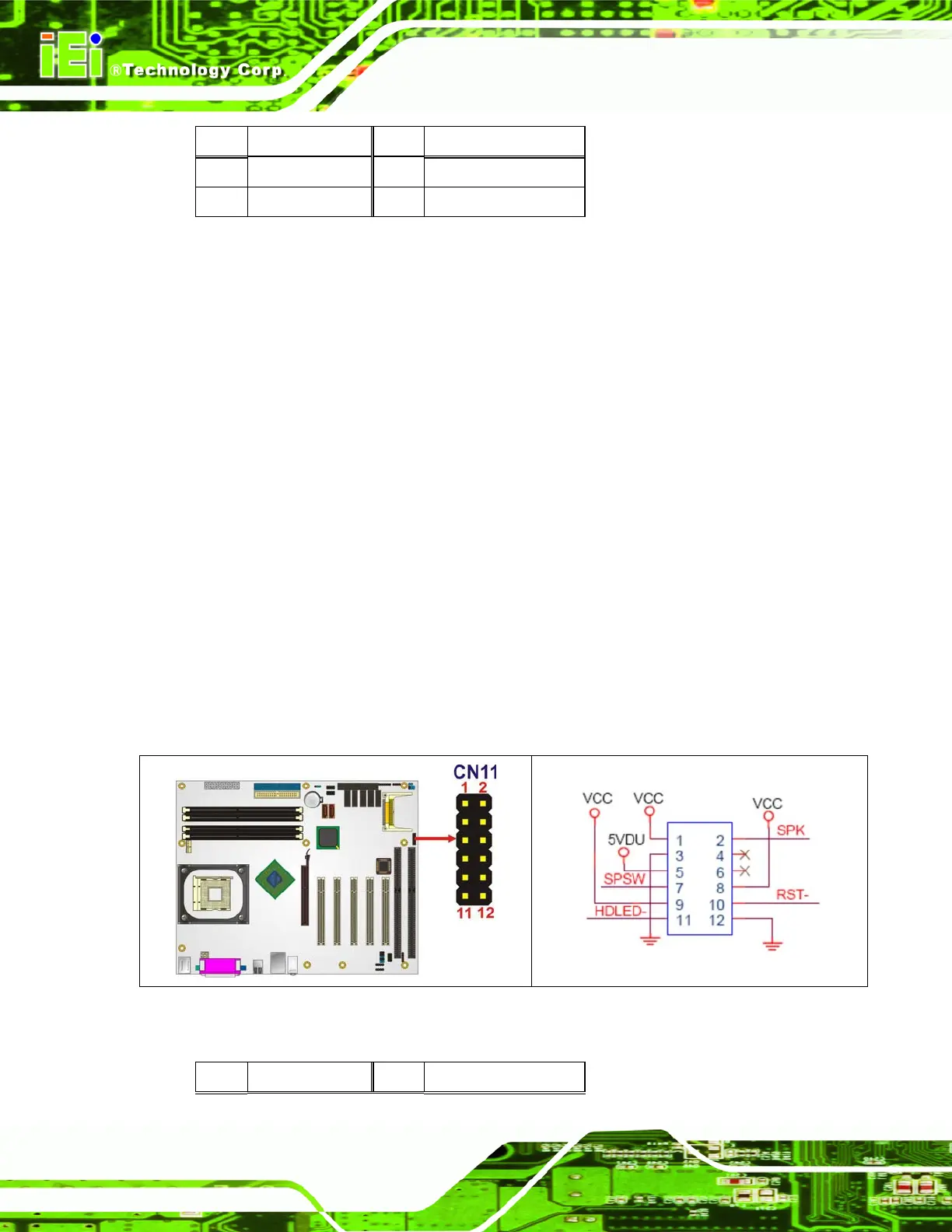
4.2.10 Front Panel Connector (12-pin)
CN Label:
CN11
CN Type:
12-pin header (2x6)
CN Location:
See
Figure 4-11
CN Pinouts:
See
Table 4-12
The front panel connector connects to external switches and indicators to monitor and
controls the motherboard. These indicators and switches include:
Power button
Reset button
Speaker
Power LED
HDD LED
Figure 4-11: Front Panel Connector Pinout Locations
PIN DESCRIPTION PIN DESCRIPTION

Table of Contents

Other manuals for IEI Technology IMBA-8650

Questions and Answers:

Question and Answer IconNeed help?

Do you have a question about the IEI Technology IMBA-8650 and is the answer not in the manual?

IEI Technology IMBA-8650 Specifications

General IconGeneral
BrandIEI Technology
ModelIMBA-8650
CategoryMotherboard
LanguageEnglish

Related product manuals