EasyManuals Logo

IEI Technology IMBA-8650 User Manual

Default Icon
248 pages
To Next Page IconTo Next Page
To Previous Page IconTo Previous Page
Page #106 background imageLoading...
Page #106 background image
IMBA-8650 Motherboard
Page 86
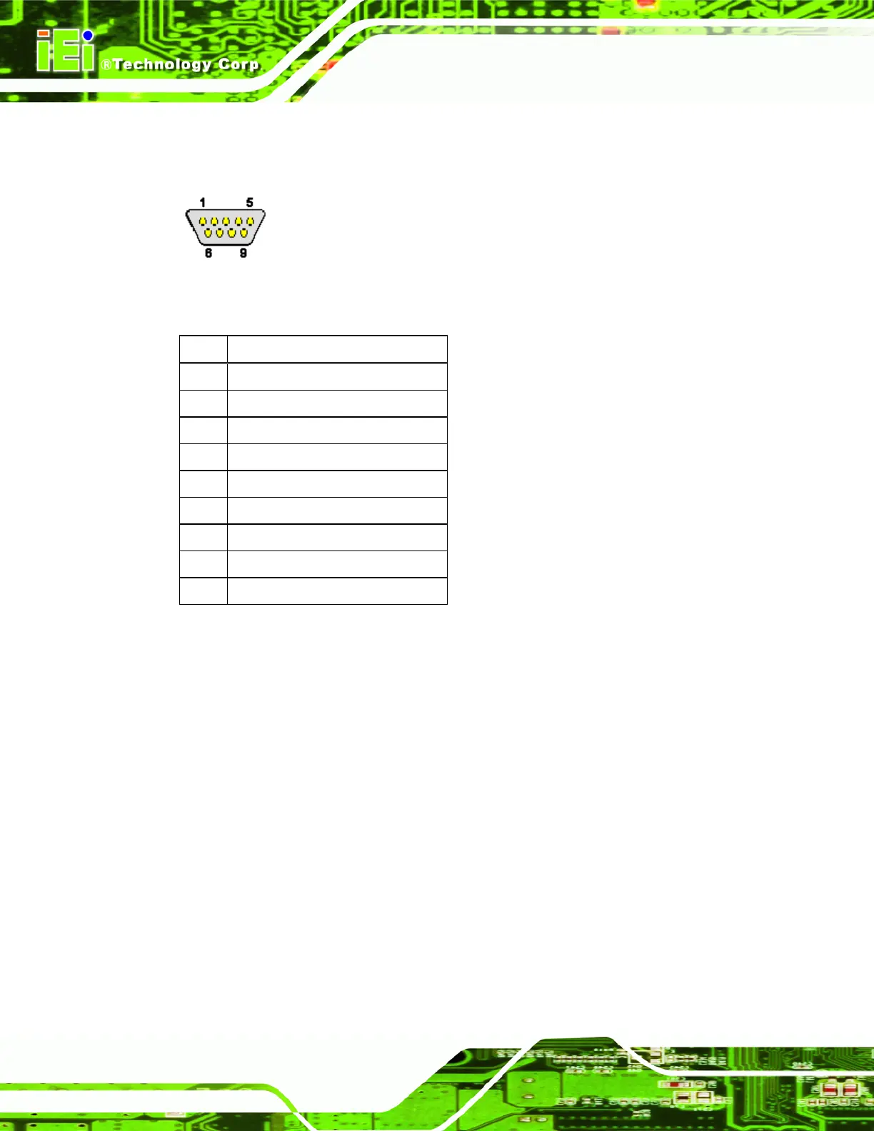
The serial connector on the external interface panel provides serial connection in the
RS-232 mode.
Figure 4-29: Serial Communications Connector Pinout Locations
PIN DESCRIPTION
1 DATA CARRIER DETECT (DCD)
2 RECEIVE DATA (RXD)
3 TRANSMIT DATA (TXD)
4 DATA TERMINAL READY (DTR)
5 GROUND (GND)
6 DATA SET READY (DSR)
7 REQUEST TO SEND (RTS)
8 CLEAR TO SEND (CTS)
9 RING INDICATOR (RI)
Table 4-28: COM1 RS-232 Mode Connector Pinouts
4.4 On-board Jumpers
The IMBA-8650 has three on-board jumpers. Refer to Section 5.3.4 for jumper
configuration settings.

Table of Contents

Other manuals for IEI Technology IMBA-8650

Questions and Answers:

Question and Answer IconNeed help?

Do you have a question about the IEI Technology IMBA-8650 and is the answer not in the manual?

IEI Technology IMBA-8650 Specifications

General IconGeneral
BrandIEI Technology
ModelIMBA-8650
CategoryMotherboard
LanguageEnglish

Related product manuals