IMBA-8650 Motherboard
Page 83
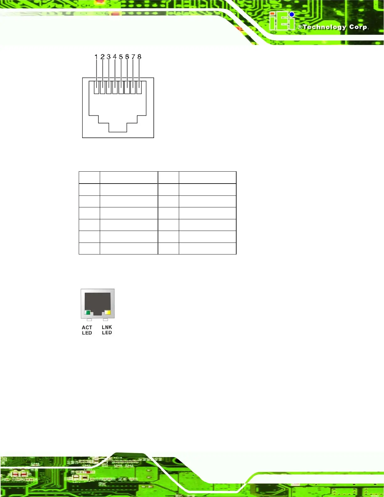
Figure 4-25: Ethernet Connector Pinout Locations
PIN DESCRIPTION PIN DESCRIPTION
1 TX0+ 7 TX3+
2 TX0- 8 TX3-
3 TX1+ 9 Active +
4 TX1- 10 Active -
5 TX2+ 11 LINK +
6 TX2- 12 LINK -
Table 4-25: Ethernet Connector Pinouts
Figure 4-26: Ethernet Connector
The RJ-45 Ethernet connector has two status LEDs, one green and one yellow. The green
LED indicates activity on the port and the yellow LED indicates the port is linked
(
Table 4-26).
 Loading...


