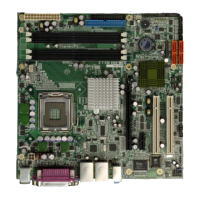
IMBA-8650 Motherboard
Page xiii
List of Figures
Figure 1-1: IMBA-8650 ..................................................................................................2
Figure 1-2: IMBA-8650 Overview .................................................................................4
Figure 2-1: IMBA-8650 Dimensions (mm).................................................................10
Figure 2-2: External Interface Panel Dimensions (mm)...........................................11
Figure 2-3: Data Flow Block Diagram........................................................................12
Figure 2-4: CPU ...........................................................................................................13
Figure 2-5: Intel® 865G Northbridge .........................................................................14
Figure 2-6: 184-pin DIMM Sockets.............................................................................16
Figure 2-7: Integrated Graphics.................................................................................17
Figure 2-8: Intel® ICH5 Southbridge .........................................................................20
Figure 2-9: Onboard Audio.........................................................................................21
Figure 2-10: IDE Interface...........................................................................................22
Figure 2-11: LPC Interface..........................................................................................23
Figure 2-12: PCI Interface...........................................................................................23
Figure 2-13: SATA .......................................................................................................24
Figure 2-14: USB .........................................................................................................25
Figure 2-15: Gigabit Ethernet.....................................................................................27
Figure 2-16: PCI-to-ISA Bridge...................................................................................28
Figure 2-17: LPC Bus..................................................................................................29
Figure 2-18: BIOS ........................................................................................................30
Figure 2-19: Super I/O.................................................................................................31
Figure 2-20: Super I/O Serial Ports............................................................................33
Figure 2-21: Super I/O Parallel Port...........................................................................34
Figure 2-22: Super I/O Infrared Port..........................................................................35
Figure 2-23: Super I/O Floppy Disk Drive Controller...............................................36
Figure 2-24: Super I/O Keyboard and Mouse Controller.........................................37
Figure 2-25: Fintek Serial Port Chipset.....................................................................37
Figure 4-1: Connector and Jumper Locations .........................................................48
 Loading...
