Invacare®LiNX
AssignOutputtoSwitch
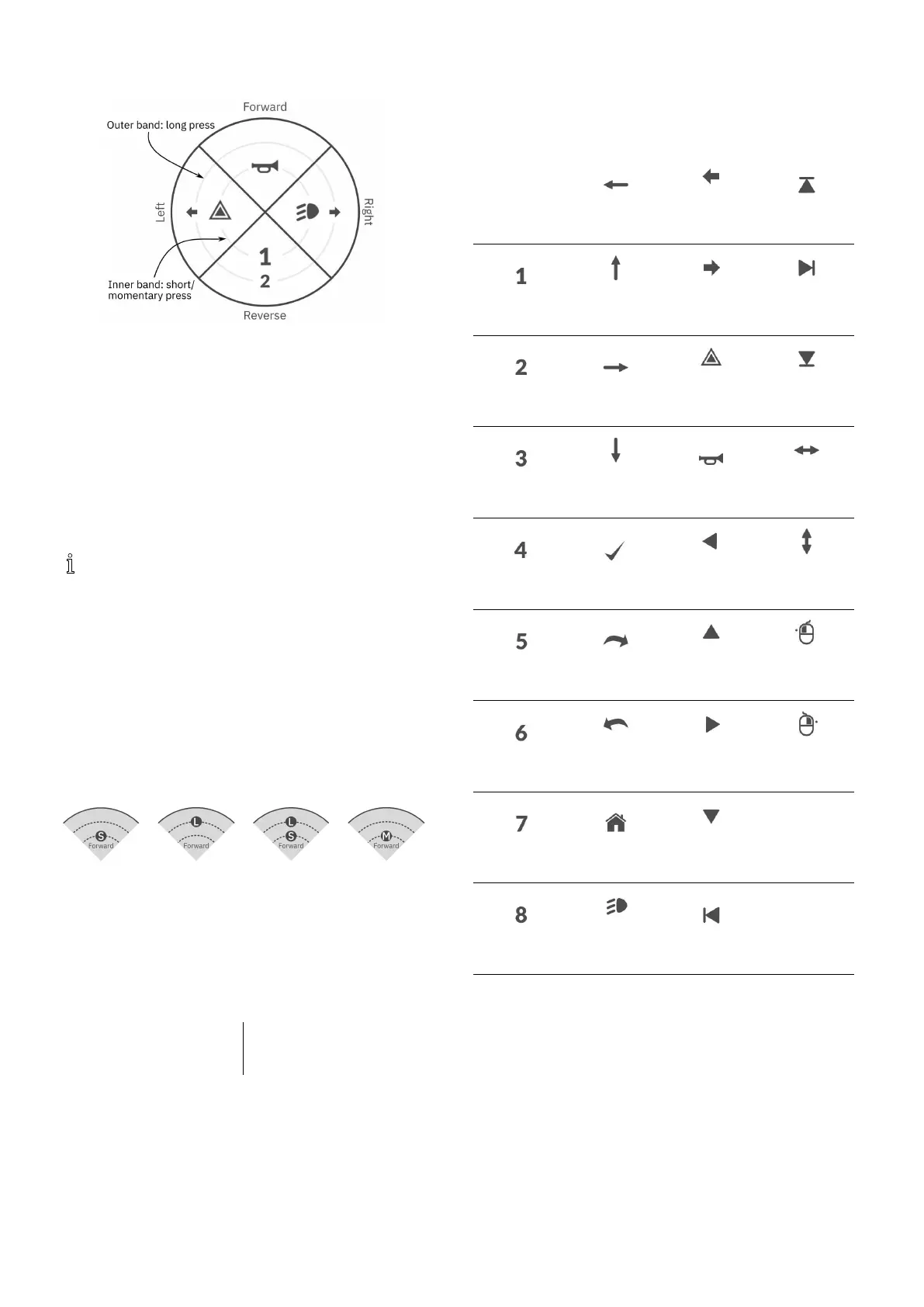
Fig.8-20Activationquadrantsandbands
Switchesarerepresentedonautilitycardwithicons
locatedontwocircularactivationbandswithinfour
quadrants.Thequadrantandthepositionoftheiconsin
thebandsindicatestotheuserhowtoselectandoperate
theswitcheswiththesystemcontrolinput.
Theinnerandouteractivationbandscorrespondtoone
ohthethreeswitchtypes:shortpress,langpressand
momentarypress.Shortandmomentarypressesare
placedontheinnerbandandlongpressesareplacedon
theouterband.
Thetermsshortpressandlongpressrefertothe
durationthatthesystemcontrolinputisactivated,
nothowfaritisdeected.Theactivationtimeto
distinguishbetweenshortpressandlongpresscan
bechangedinuserpreferences,see5.2.1Overview
UserPreferences,page60.
Becauseitisdifculttodiscernthedifferencebetweena
longpressandamomentarypress,aquadrantcongured
foramomentarypress(innerband)cannotbecongured
alsowithalongpress(outerband)switch.Thismeans,
foranyquadrantcongurationwithamomentaryswitch,
theouterbandwillbeempty.Thecongurationoptions
areshownbelow.
Fig.8-21Short
pressonly
Fig.8-22Long
pressonly
Fig.8-23Short
andlongpress
Fig.8-24
Momentary
only
SetOutputBehaviour
Sethowtheoutputbehaveswhenswitched,basedonthe
switch’squadrantandactivationringposition.Eachoutput
canbeconguredasalatchingornon-latchingoutputtype.
Therearethreelatchingtypesandonenon-latchingtype.
Non-latchingLatching
Momentary
LatchON,LatchOFF,Toggle
Choose:
•Momentarytoactivateanoutputfortheduration
thattheswitchisselected.
•LatchONtoactivateanoutputandremainactivated
whentheswitchisdeselected.
•LatchOFFtodeactivateanoutputandremain
deactivatedwhentheswitchisdeselected.
•Toggletochangethecurrentoutputstate(activated
–>deactivatedordeactivated–>activated)and
remaininthenewstatewhentheswitchisdeselected.
SelectDisplayIconforSwitch
None
LeftArrow
LeftTurn
Signal
LatchedUp
One
Forward
Arrow
RightTurn
Signal
Latched
Right
TwoRightArrow
Hazard
Lights
Latched
Down
Three
Reverse
Arrow
Horn
Left-Right
Arrow
FourSelect
Momentary
Left
Up-Down
Arrow
FiveNext
Momentary
Up
MouseClick
Left
Six
Previ-
ous/Back
Momentary
Right
MouseClick
Right
SevenHome
Momentary
Down
Eight
Position
Light
LatchedLeft
Torepresenttheoutput,selectadisplayiconforthe
switchineithertheinnerorouteractivationbandinone
ofthesystemcontrolinput’sfourquadrants(forward,
reverse,leftorright)
ExampleofAddingOutput
Thefollowinginstructionshowsyouhowtoprogram
therstcontroloutputofDLX-OUT500usinga
short/momentarypressforwardsasanexample.
1.OpenFunctions.
2.Addnewutilityfunctionoropenexistingutility
function.See8.1ProleAndFunctionActions,page
85.
941605129-G