GENERAL
Repair of the electrical system, for the most part, is
limited to the replacement of faulty components or wir-
ing. Wiring diagrams and Component Location illus-
trations are provided in Section 10N for troubleshoot-
ing and/or testing the electrical system. Specific repair
and replacement instructions, where applicable, are
also provided in this section.
NOTE
The test instrument shown in the illustrations for
this section is a digital multimeter (DMM). How-
ever, any test instrument capable of measuring
voltage, current resistance, and continuity val-
ues specified for each test is acceptable.
NOTE
See Engine Manufacturer’s Service Manual for
information on engine electrical components not
covered in this section.
In addition to testing a suspected faulty component it
may be necessary to check for shorts or breaks in the
wiring to the component. A common method of testing
wires or circuits is to perform a continuity check as
described below.
NOTE
Before performing any component or wiring test,
check for corrosion and loose or missing con-
nections.
If a component (switch, relay, etc.) is removed for test
or replacement make sure to identify and label wires
so that the component can be installed correctly.
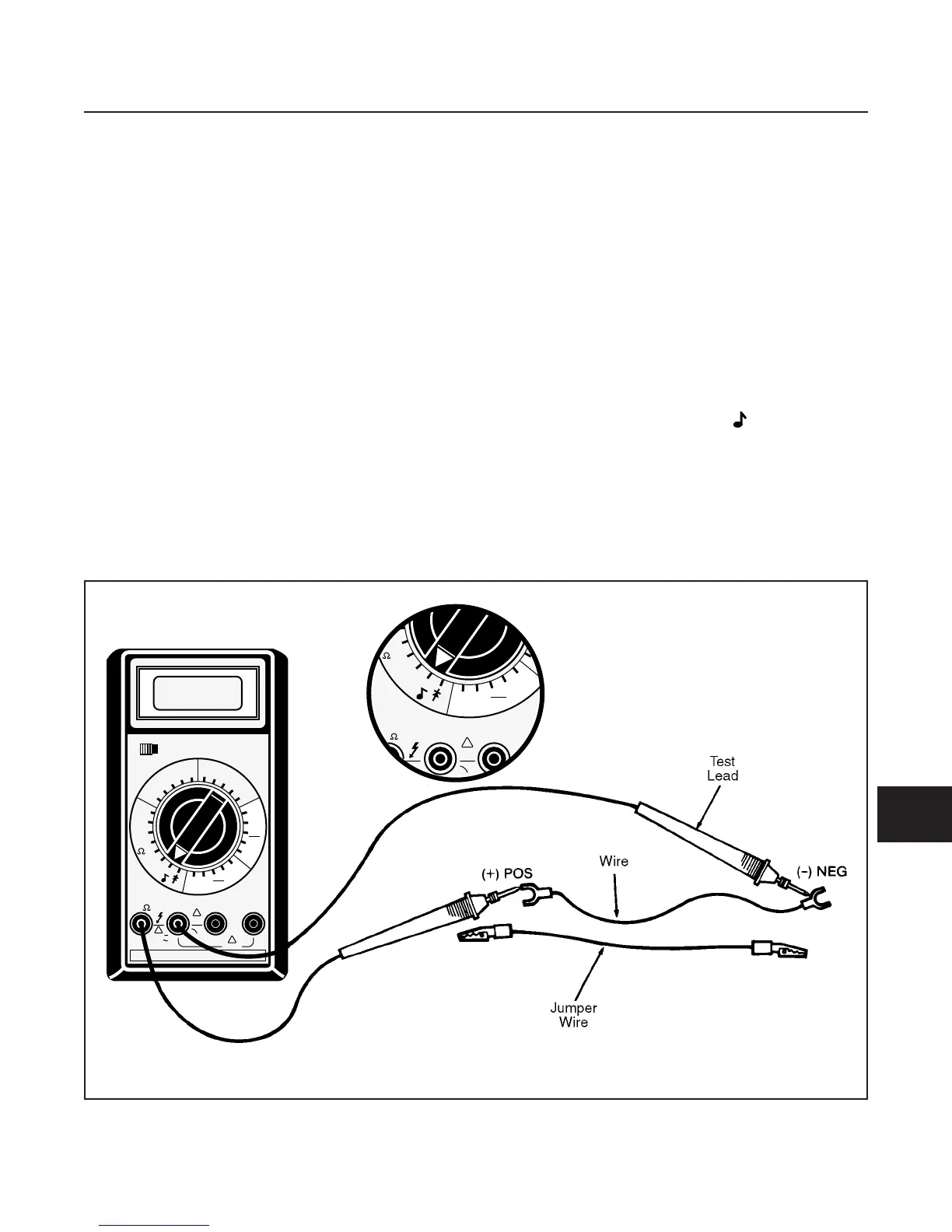
WIRE CONTINUITY TEST
(See Figure 10C-1)
1. Identify and locate the wire to be checked on the
appropriate “Electrical System” illustration, locat-
ed in Section 10N.
2. Set multimeter to Ω (ohms) scale and touch
leads to end of wire.
•
There should be a reading (continuity) on the
multimeter. If not, proceed to 3.
3. Perform a second check by using a jumper wire to
bypass the wiring being tested. If the component
in question now functions normally, replace the
original wire.
ELECTRICAL SYSTEM
SECTION 10C. GENERAL INSTRUCTIONS
10C-1
10C