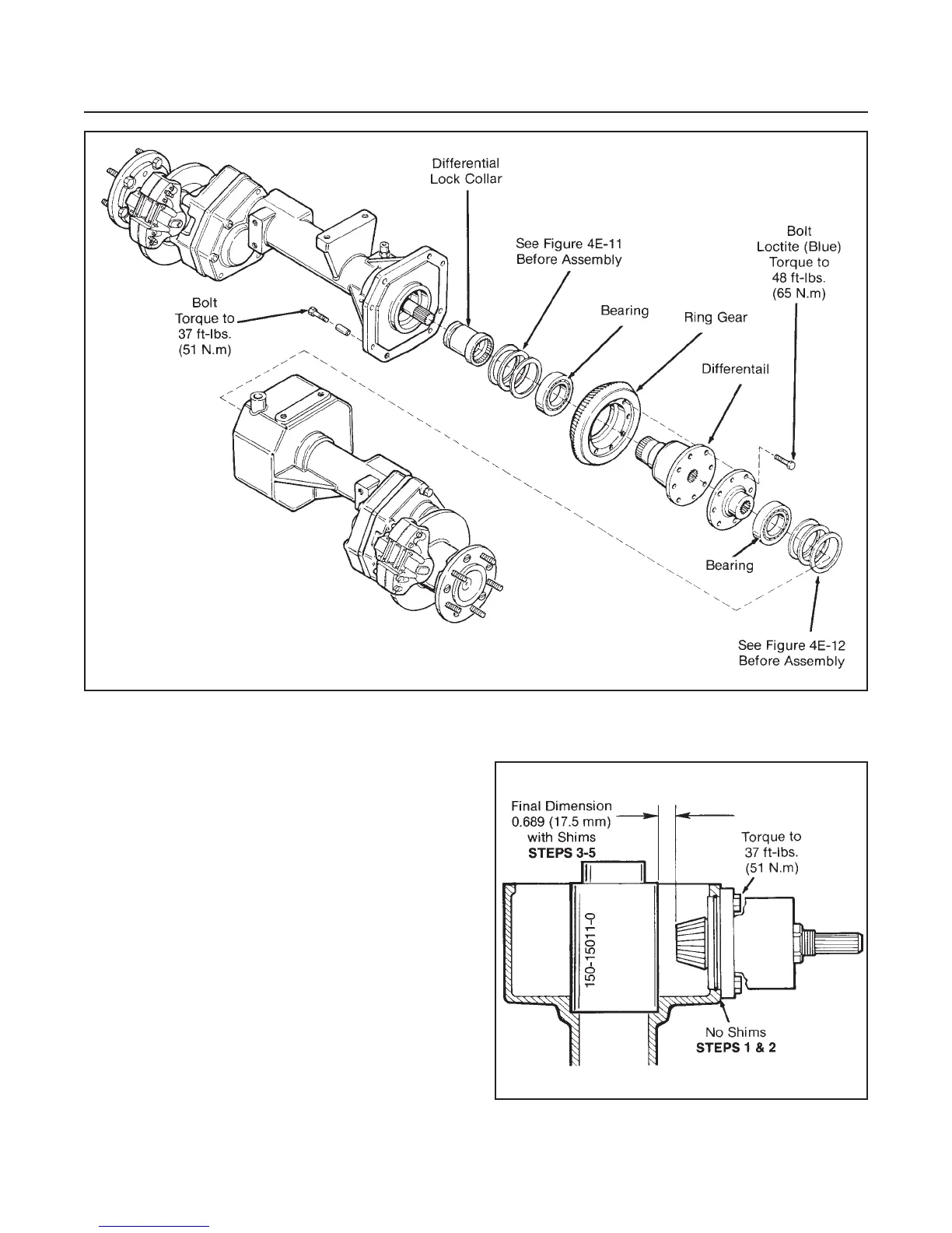
INPUT BEVEL PINION AND RING
GEAR CLEARANCE (See Figure 4E-10)
NOTE
Proceed with the following steps if a new matched
input bevel pinion and ring gear are to be installed.
1. Install input bevel pinion assembly with no shims
and torque it to 37 ft-lbs. (51 N.m).
2. Install special tool into bearing bore of gear case.
3. Measure the distance between the special tool
and end of pinion.
4. Subtract this dimension from 0.689" (17.5 mm).
5. Build a shim pack equal to the final dimension ob-
tained in Step 4.
6. Remove and install shim pack to the input bevel
pinion housing.
7. Remove special tool and proceed with Differential,
Pinion and Ring Gear Backlash Adjustment.
DRIVE TRAIN
SECTION 4E. AXLE
4E-8
Figure 4E9. Differential Reassembly
Figure 4E-10. Input Bevel Pinion and
Ring Gear Clearance