GENERAL
This section provides instructions for testing the vari-
ous switches that are part of the electrical system.
Repair is limited to replacement of components found
faulty during testing. See Figure 10N for location of
components.
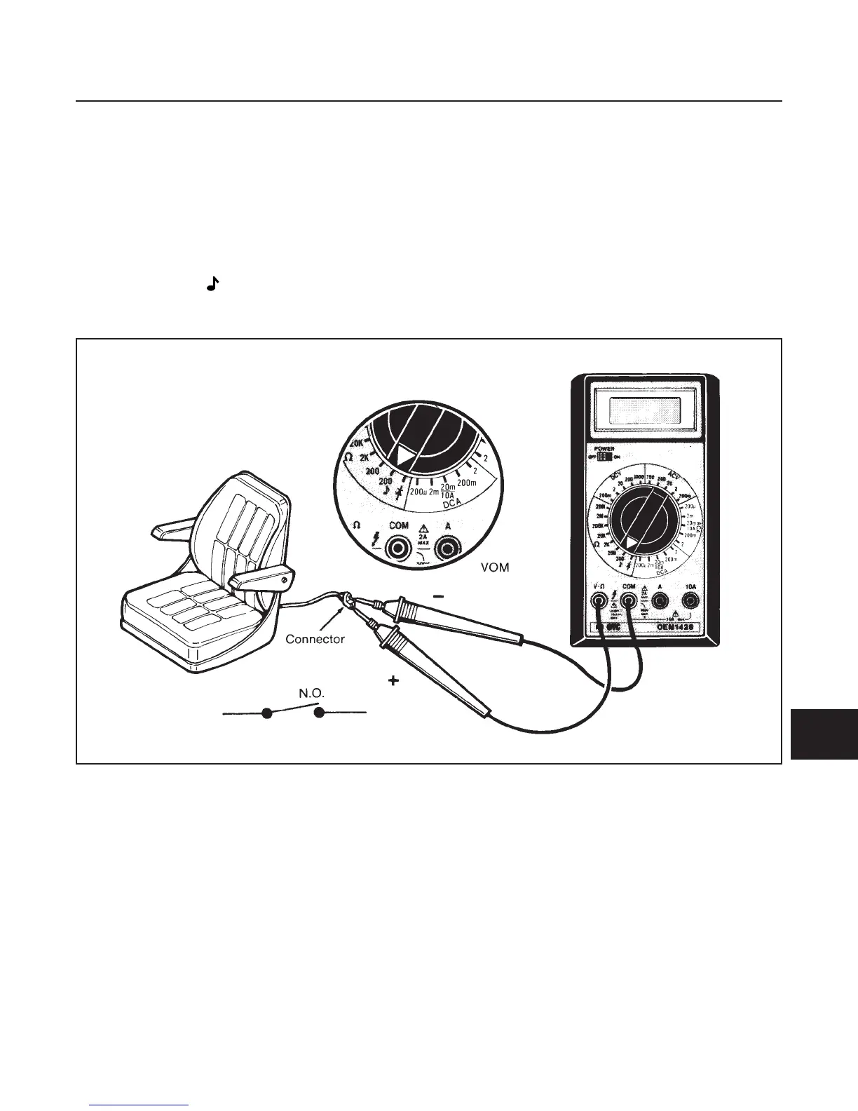
SEAT SWITCH TEST (See Figure 10G-1)
1. Disconnect seat switch connector.
2. Set VOM to 200 Ω (ohms) scale.
3. Connect meter leads to connector terminals.
•
There should be no reading (no continuity) on
VOM.
4. Depress seat switch.
•
There should be a reading (continuity) on VOM.
Replace a switch that does not meet all the above
test results or has resistance of 0.5 Ω (ohms) or more.
ELECTRICAL SYSTEM
SECTION 10G. SWITCHES
10G-1
10G
Figure 10G-1. Seat Switch Test
 Loading...


