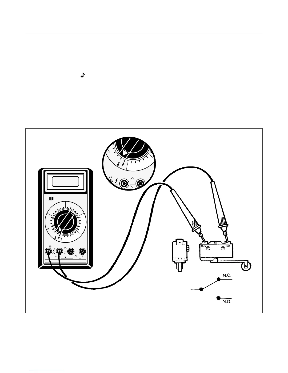
NEUTRAL AND REVERSE SENSING
SWITCH TEST (See Figure 10G-14)
1. Disconnect ground cable at battery.
2. Identify (label) and disconnect electrical leads at
switch.
3. Set multimeter to 200 Ω (ohms) scale.
4. Connect leads as shown.
•
There should be a reading on multimeter (conti-
nuity).
5. Depress switch lever.
•
There should be no reading at multimeter (no
continuity).
6. Move test lead from NC to NO.
•
There should be no reading on the multimeter
(no continuity).
7. Depress switch lever.
•
There should be a reading on multimeter (conti-
nuity).
Replace a switch that does not meet all the above
test results or has resistance of 0.5 Ω (ohms) or more.
ELECTRICAL SYSTEM
SECTION 10G. SWITCHES
10G-14
Figure 10G-14. Neutral and Reverse Switch Test