EasyManuals Logo

Jacobsen HR5111 User Manual

Jacobsen HR5111
339 pages
To Next Page IconTo Next Page
To Previous Page IconTo Previous Page
Page #255 background imageLoading...
Page #255 background image
GLOW PLUG SWITCH TEST
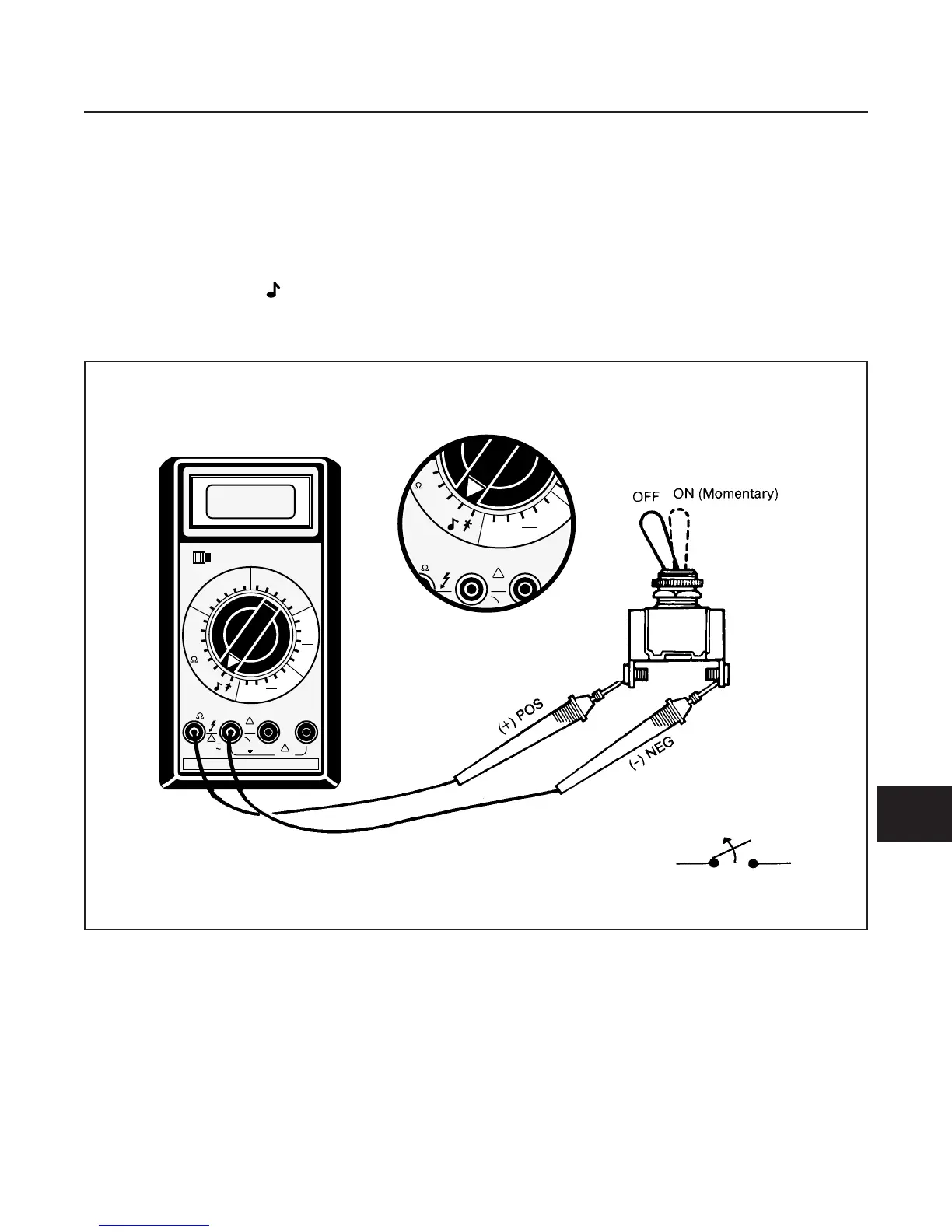
TEST SWITCH TEST (See Figure 10G-11)
The glow plug switch is pushed by the operator to allow
current flow to the glow plugs, prior to starting the
machine.
See Figure 10G-11 and test switch as follows:
1. Disconnect leads at switch.
2. Set multimeter to 200 (ohms) scale.
3. Connect multimeter test leads to switch terminals
with the switch in the OFF position.
There should be no reading on the multimeter.
4. Hold switch in the ON position.
There should be a reading of 0–0.5 (ohms)
on the multimeter.
Replace a switch that does not meet all the above
test results or has resistance of 0.5 (ohms) or more.
ELECTRICAL SYSTEM
SECTION 10G. SWITCHES
10G-11
10G
Figure 10G-11. Glow Plug Switch Test and Test Switch Test
POWER
OFF ON
200m
2
20
200
1000
750
200
20
2
200m
20M
2M
200M
20K
2K
200
200
DCV
ACV
ACA
200µ
2m
200m
2
2
200m
20m
10A
2m
200µ
DCA
20m
10A
COM A 10A
!
1000V
750V
MAX
!
!
2A
MAX
10A MAX
500V
MAX
200m
2
20
200
1000
750
200
20
2
200m
20M
2M
200M
20K
2K
200
200
DCV
ACV
ACA
200µ
2m
200m
2
2
200m
20m
10A
2m
200µ
DCA
20m
10A
COM A
!
2A
MAX
V -
-

Table of Contents

Questions and Answers:

Question and Answer IconNeed help?

Do you have a question about the Jacobsen HR5111 and is the answer not in the manual?

Jacobsen HR5111 Specifications

General IconGeneral
BrandJacobsen
ModelHR5111
CategoryLawn Mower
LanguageEnglish

Related product manuals