BREAK-AWAY TORQUE ADJUSTMENT
(See Figure 4E-5)
NOTE
The following adjustment is made with no seal
installed in the pinion housing.
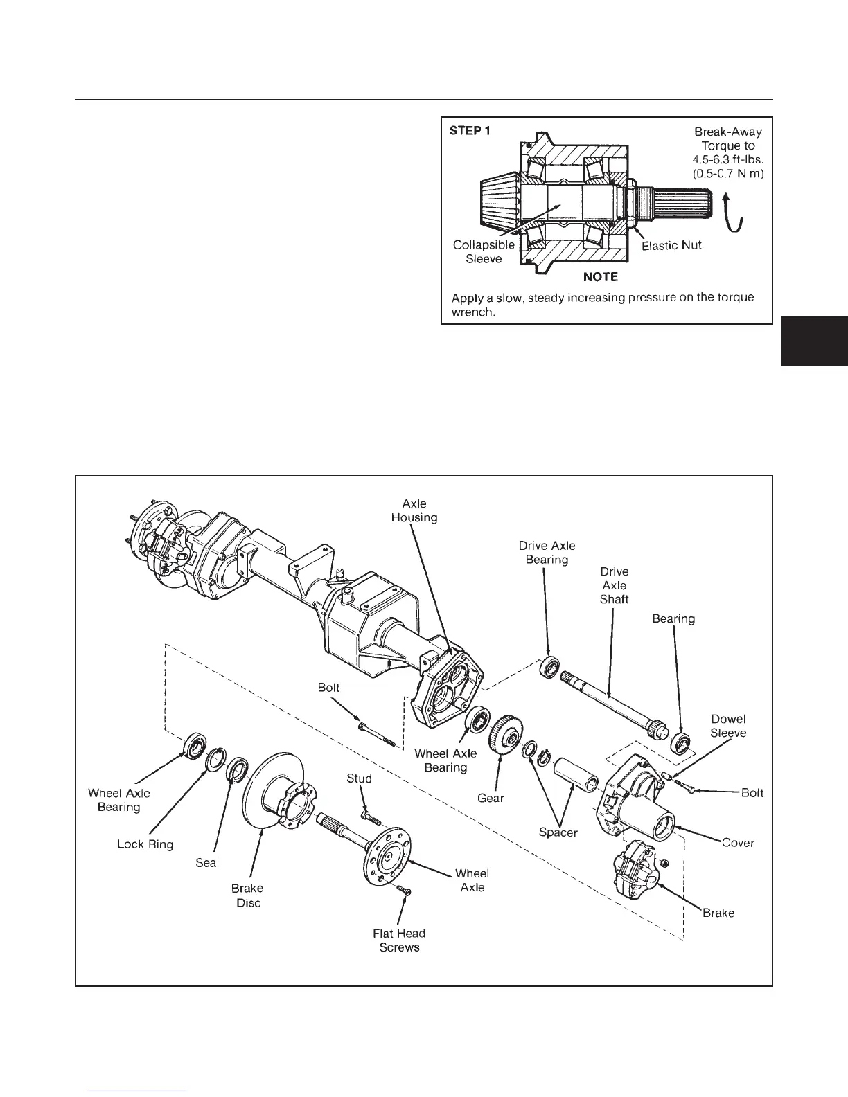
1. Tighten the elastic nut until a break-away torque
of 4.5–6.3 in-lbs. (0.5–0.7 N.m) is obtained.
NOTE
Apply a slow steady increasing pressure on the
torque wrench.
2. Install the seal in the pinion housing.
3. Install O-ring and shims pack on pinion housing.
REDUCTION GEAR AND DRIVE AXLE
GENERAL
Bearings in the reduction gear case are press fitted.
The large gear is splined to the shaft. The axle pinion
gear is part of the axle shaft.
DISASSEMBLY (See Figure 4E-6)
NOTE
Remove the drive axle only if necessary.
When removing the right axle shaft the differential col-
lar will slide off the end.
DRIVE TRAIN
SECTION 4E. AXLE
4E-5
4E
Figure 4E-6. Reduction Gear and Drive Axle Disassembly
Figure 4E-5. Break-Away Torque Adjustment