DISASSEMBLY
1. Clean exterior of motor with suitable solvent be-
fore removing the bolts.
2. Before disassembly mark motor sections, starting
at drive shaft end, to ensure correct order and po-
sition of parts when reassembling. Recommended
method of marking body sections is to use a fine
point metal punch, making one indentation for
section #1, two indentations for section #2, etc.
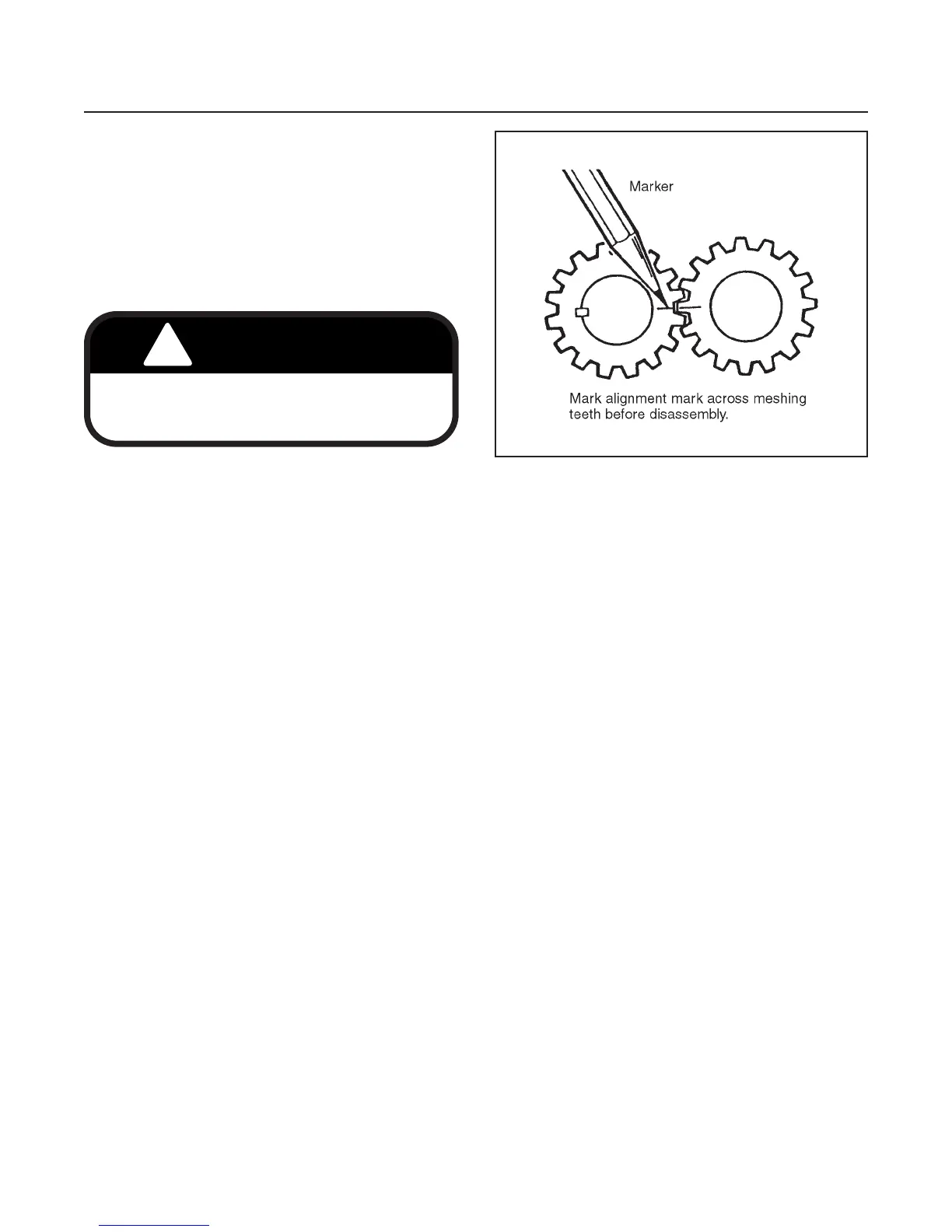
3. After removing the bolts and cover, mark a line
across meshing teeth to ensure that gears are re-
assembled in the same position (see Figure 8N-3).
4. Remove gear set.
5. Place parts in assembly order, on a clean work
area, as they are removed.
6. Discard seals as they are removed.
INSPECTION
1. Keeping parts in assembly order, clean and air dry
each for inspection. Look for metal chips or slivers
during cleaning (an indication of damage to motor
or other hydraulic component).
2. Inspect all parts for cracks, nicks, burrs and exces-
sive wear. Replace entire motor if found damaged
or worn.
REASSEMBLY (See Figure 8N-2)
1. Apply a coat of clean hydraulic oil to all parts to
ease assembly.
2. Assemble motor one section at a time, building up
from flange section.
3. Use a new seal kit during assembly. Use clean
grease to keep seals in position.
4. Remove alignment mark from gear sets after they
have been installed with teeth in mesh.
5. Rotate gear set after assembling to make sure
there is no binding between parts.
6. Install the bolts, finger tight and rotate gear set to
make sure it turns freely. Tighten tie bolts evenly
and in steps to a final torque of 26–30 ft-lbs. (35–
41 N.m).
HYDRAULICS
SECTION 8N. MOWER MOTOR
8N-2
Figure 8N-3. Marking Gear Teeth