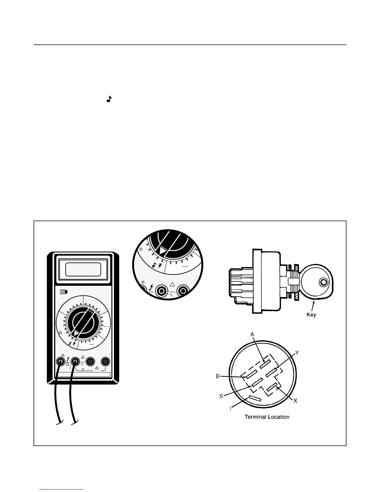
IGNITION SWITCH TEST (EARLY)
(See Figure 10G-2)
1. Disconnect ground (black) NEG (–) cable at bat-
tery.
2. Disconnect wiring connector at switch.
3. Set multimeter to 200 Ω (ohms) scale.
4. See Figure 10I-3 and check all switch positions as
follows:
a. With key switch in OFF position connect test
leads to any two terminals — check all five.
•
There should be no reading on multimeter.
NOTE
If there is a reading of more than 0.5 Ω (ohms)
in any of the following tests the switch is faulty
and must be replaced.
b. With key switch in RUN position, connect black
NEG (–) test lead to terminal B and red POS
(+) lead to terminal I.
•
There should be a reading of 0–0.5 Ω (ohms)
on the multimeter.
c. Move red POS (+) lead to terminal A.
•
There should be a reading of 0–0.5 Ω (ohms)
on the multimeter.
d. Connect black NEG (–) lead to terminal X and
red POS (+) lead to terminal Y.
•
There should be a reading of 0–0.5 Ω (ohms)
on the multimeter.
e. Hold switch in START position. Connect black
NEG (–) lead to terminal B and red POS (+)
lead to terminal I.
•
There should be a reading of 0–0.5 Ω (ohms)
on multimeter.
f. Move red POS (+) lead to terminal S.
•
There should be a reading of 0–0.5 Ω (ohms)
on multimeter.
Replace a switch that does not meet all of the above
test results or has resistance of 0.5 Ω (ohms) or more.
ELECTRICAL SYSTEM
SECTION 10G. SWITCHES
10G-2