ENGINE (FUEL) SOLENOID
HORN
CRUISE ENGAGE
CAB (See Figure 10H-1)
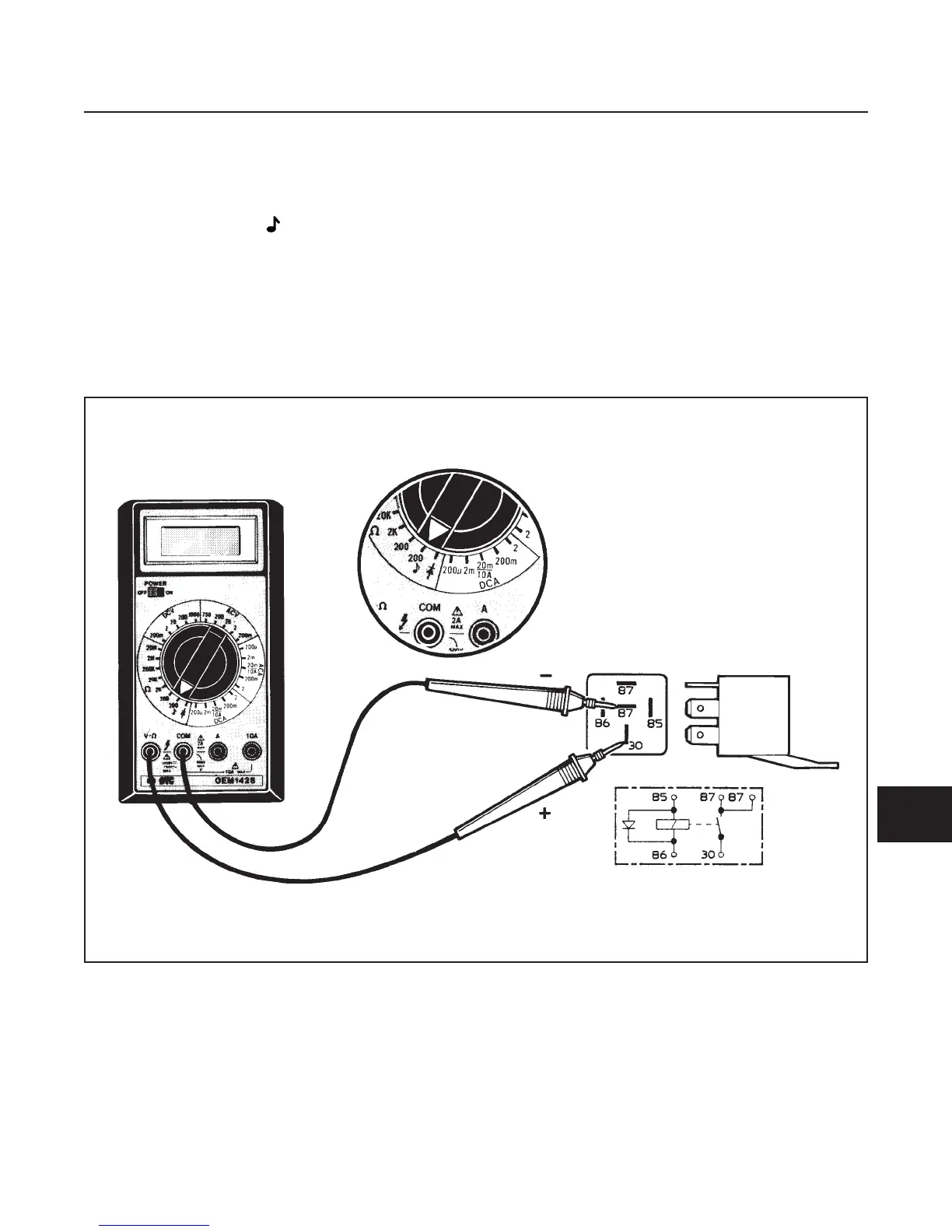
1. Set multimeter to 200 Ω (ohms) scale.
2. Connect red POS (+) lead to one of the terminals
87, then to the second terminal 87.
3. Connect black NEG (–) lead from multimeter to
terminal 30.
•
There should be no continuity on both terminals
87. If there is continuity, replace relay.
4. Connect 12V across terminals 85 and 86. There
should be an audible “click”.
5. Connect black NEG (–) lead from the multimeter
to terminal 30.
6. Connect red POS (+) lead from the multimeter to
one of the terminals 87, then to the second termi-
nal 87.
•
There should be continuity on both terminals 87.
If there is no continuity, replace relay.
ELECTRICAL SYSTEM
SECTION 10H. RELAY
10H-1
10H
Figure 10H-1. Relay Test
 Loading...


