IMPLEMENT (MOWER) SWITCH TEST
(EARLY) (See Figure 10G-6)
NOTE
See page 10G-23 for later switch.
1. Disconnect switch connectors.
2. Set multimeter to 200 Ω (ohms) scale.
3. With switch in OFF position, test as follows:
a. Connect one multimeter test lead to terminal A
and the other lead to B.
•
There should be 0–0.5 Ω (ohms) on the mul-
timeter.
b. Connect one multimeter test lead to terminal E
and the other to terminal F.
•
There should be 0–0.5 Ω (ohms) on the mul-
timeter.
c. Check for continuity across all remaining com-
binations of terminals (with switch in the OFF
position).
•
There should be no reading on the multimeter.
4. Place switch in ON position and test as follows:
a. Check for continuity by connecting one multi-
meter test lead to terminal B and the other to
terminal C.
•
There should be 0–0.5 Ω (ohms) on the mul-
timeter.
b. Check for continuity across all remaining com-
binations of terminals (with switch in the ON
position).
•
There should be no reading on the multimeter.
Replace a switch that does not meet all the above
test results or has resistance of 0.5 Ω (ohms) or more.
ELECTRICAL SYSTEM
SECTION 10G. SWITCHES
10G-6
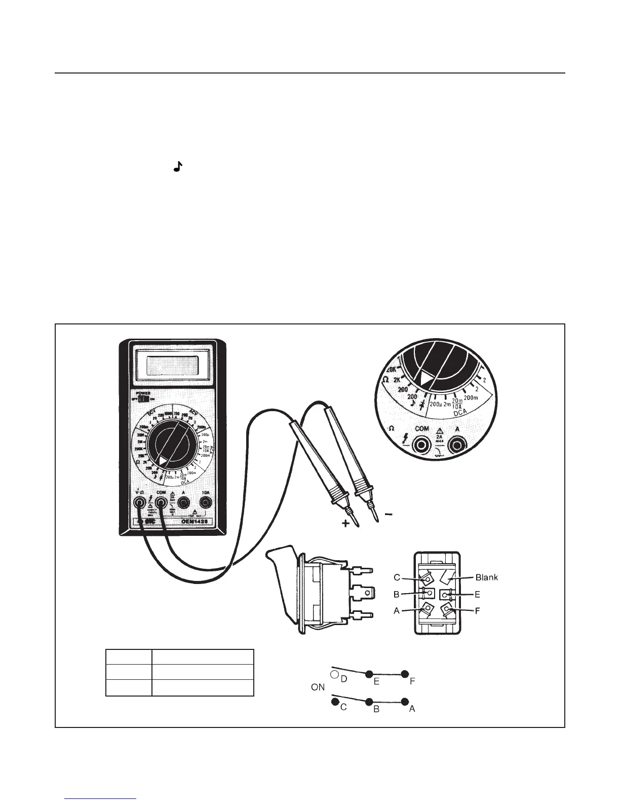
Figure 10G-6. Implement (Mower) Switch Test
Position Continuity
OFF A and B E and F
ON B and C
 Loading...


