ROTOR COIL, SLIP RING AND BRUSH TEST
(See Figure 10E-4)
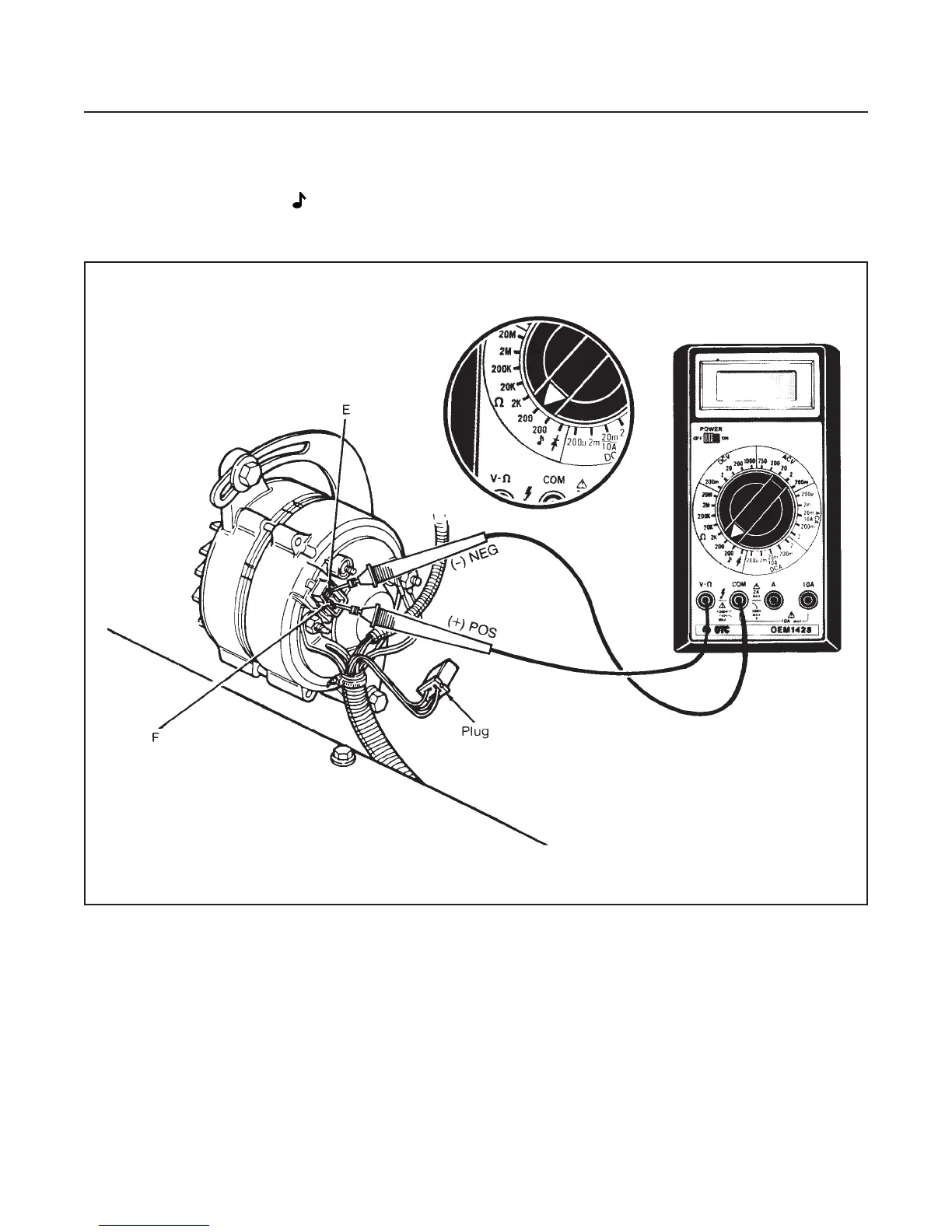
1. Remove the plug from the alternator.
2. Set the multimeter to 200 Ω (ohms) range.
3. Connect the multimeter POS (+) lead to terminal
F and the NEG (–) lead to terminal E.
•
The resistance should be approximately 6.5–10
Ω (ohms).
ELECTRICAL SYSTEM
SECTION 10E. CHARGING SYSTEM
10E-4
Figure 10E-4. Rotor Coil, Slip Ring and Brush Test
 Loading...


