2. After removing tie bolts, disassemble pump one
section at a time. Before removing gear sets,
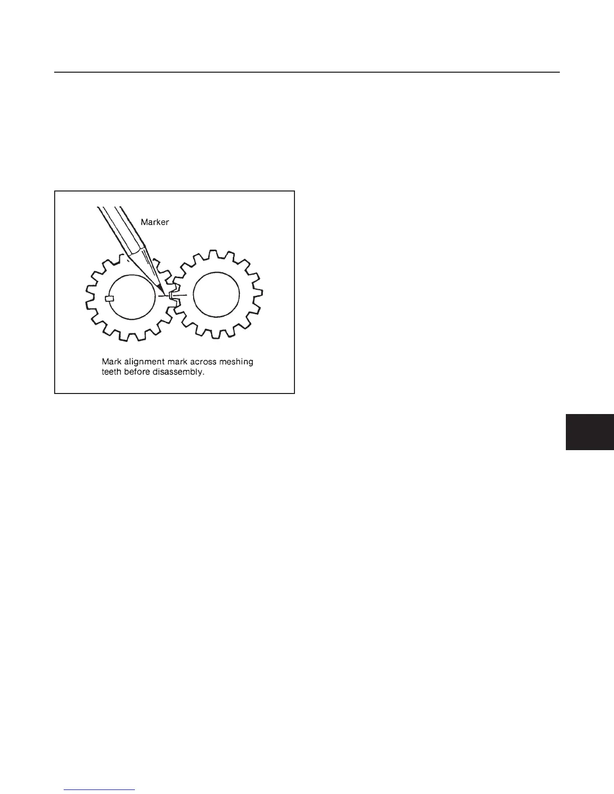
mark a line across meshing teeth to ensure that
gears are reassembled in the same position (see
Figure 8E-3).
3. Place parts in assembly order, on a clean work
area as they are removed.
4. Discard seals and gaskets as they are removed.
INSPECTION
1. Keeping parts in assembly order, clean and air dry
each for inspection. Look for metal chips or slivers
during cleaning (an indication of damage to pump
or other hydraulic components).
2. Inspect all parts for cracks, nicks, burrs and ex-
cessive wear. Replace all damaged parts. Gears
must be replaced in sets.
3. Inspect wear plates, replace if worn or damaged.
REASSEMBLY (See Figure 8E-2)
1. Apply a coat of clean hydraulic oil to all parts to
ease assembly.
2. Assemble pump one section at a time, building up
from cover section.
3. Use a new seal kit during assembly. Use clean
grease to keep seals in position.
4. Remove alignment mark from gear sets after they
have been installed with teeth in mesh.
5. Rotate drive shaft after assembling each section
to make sure there is no binding between parts.
6. Use extreme care when installing shaft seal. It must
seat squarely in seal bore with metal casing fac-
ing out. Use clean grease on shaft and put tape
over keyway to avoid cutting seal during assembly.
7. Install the bolts finger tight and rotate drive shaft
to make sure it turns. Tighten tie bolts evenly and
in steps to a final torque of 31–35 ft-lbs. (42–47
N.m).
8. Apply permatex 2 to both sides of gasket surface
of flange.
9. Install gasket and flange.
INSTALLATION (See Figure 8E-1)
1. Position the pump on the hydrostatic pump.
2. Turn pump slightly to engage spline of pump coupler.
3. Securely fasten in place with attaching hardware.
4. Connect hydraulic lines.
HYDRAULICS
SECTION 8E. IMPLEMENT PUMP
8E-3
8E
Figure 8E-3. Marking Gear Teeth
 Loading...


