GENERAL
The 35 amp charging system consists of an alternator
and separate regulator.
See the Engine Manufacturer’s Service Manual for de-
tailed repairs of the alternator.
ALTERNATOR FIELD TEST
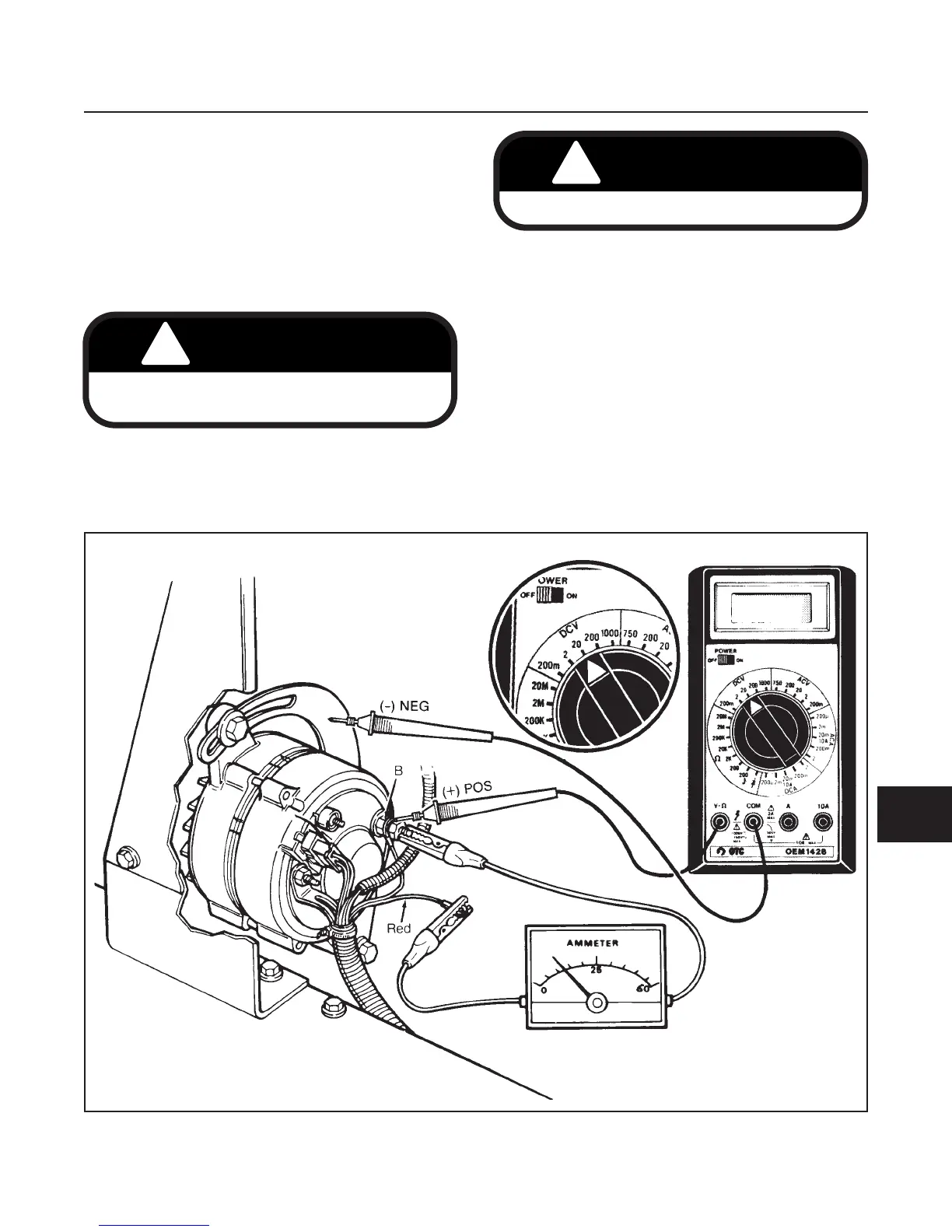
OUTPUT CURRENT (See Figure 10E-1)
1. Remove the red wire from terminal B of the alter-
nator.
2. Connect an ammeter and voltmeter as shown.
3. Start the engine.
•
As engine rpm increases, voltage should increase
to a maximum 14V at 1500 engine rpm.
•
Current output should also increase to a maxi-
mum 35 amps at 2500 engine rpm.
NOTE
Charge condition of battery will affect current
(amp) output. As the battery begins to charge,
the current output will slowly decrease.
•
If no voltage and/or current is measured, the
alternator is faulty.
ELECTRICAL SYSTEM
SECTION 10E. CHARGING SYSTEM
10E-1
10E
Before installing test instruments, disconnect the
negative battery cable from the battery.