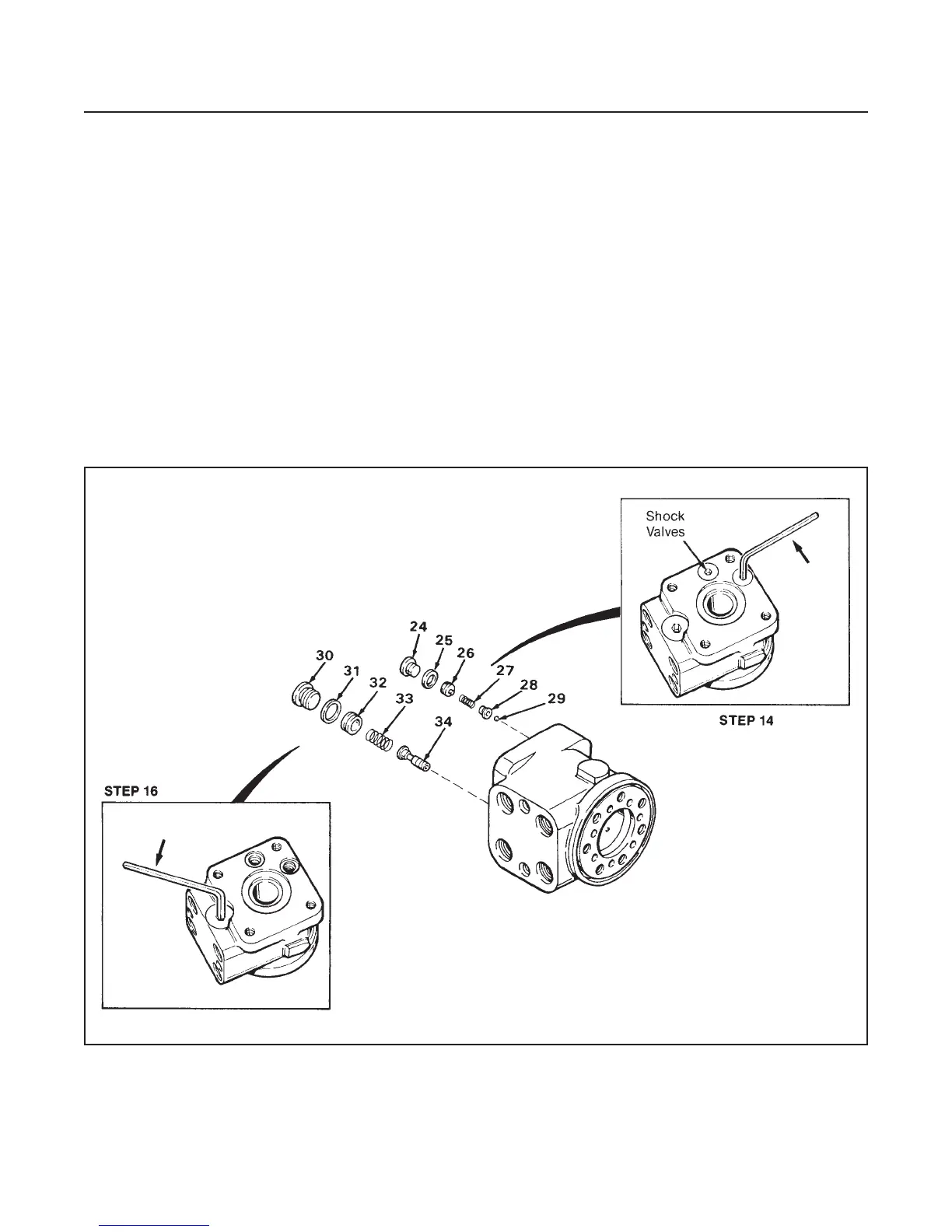
(See Figure 6C-6)
NOTE
If either shock valve plugs (26) in Step 15 and/or
the relief valve plug (32) in Step 17 are removed,
the relief setting will be destroyed.
If it is not necessary to remove these items, skip
Steps 14–17.
14. Use a 6 mm hex socket wrench. Remove shock
valve plug (24) and washer (25).
15. Remove plug (26), spring (27), valve cone (28) and
ball (29).
NOTE
Steps 14 and 15 describe the removal of one of
two shock valve assemblies. Repeat Steps 14
and 15 for the other shock valve.
16. Using a 8 mm hex socket wrench, remove pres-
sure relief valve plug (30) and washer (31).
17. Remove plug (32), spring (33) and valve spool (34).
INSPECTION
1. Clean all parts being careful not to scratch or nick
parts. After cleaning, coat parts with a thin film of
oil.
2. Inspect parts for signs of wear or damage. Dis-
card all seals and O-rings.
3. Replace any damaged or worn parts.
STEERING
SECTION 6C. STEERING UNIT
6C-4
Figure 6C-6.