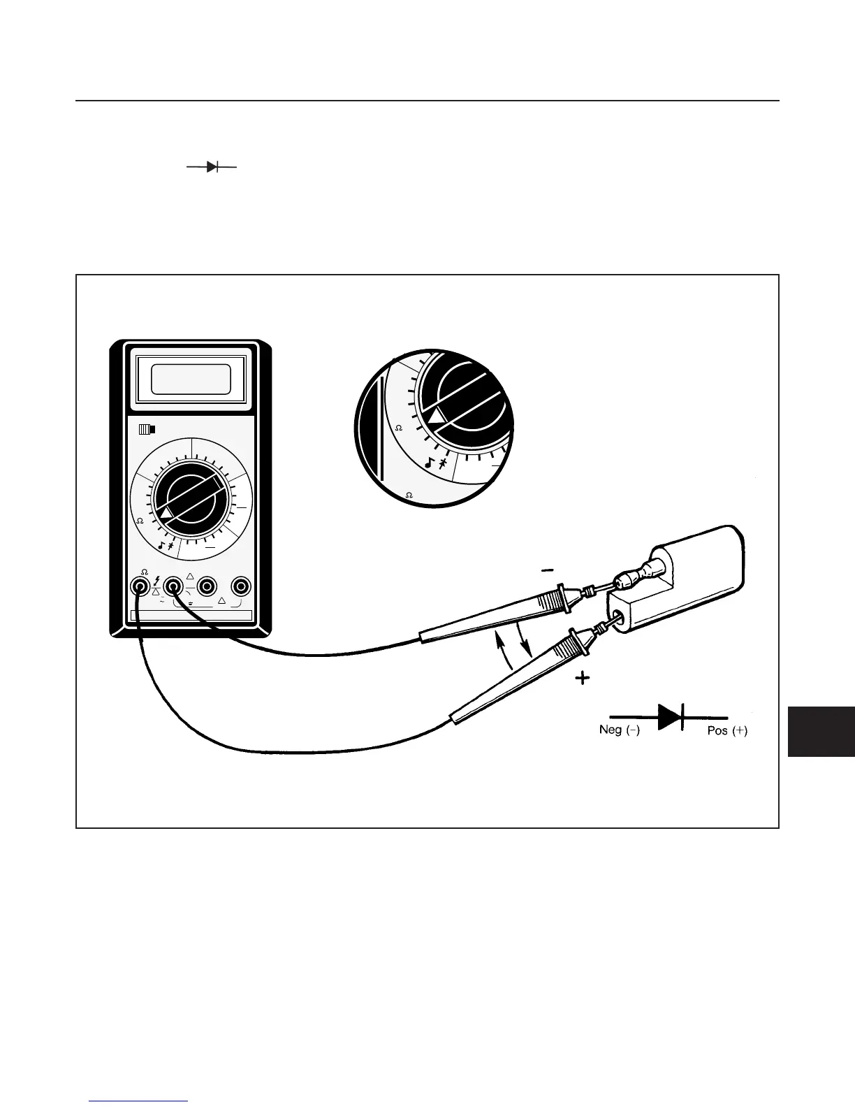
EasyManua.ls Logo

Jacobsen HR5111 - 10 M. Diode Test

Jacobsen HR5111
339 pages
Print Icon
To Next Page IconTo Next Page
To Previous Page IconTo Previous Page
Loading...
DIODE TEST
See Figure 10M-1 and test diode as follows:
1. Set meter to scale.
2. Connect meter leads to diode as shown.
There should be a reading (continuity on the meter
scale.
3. Reverse the POS (+) and NEG (–) test leads.
There should be no continuity.
If continuity registers in both positions, the diode
is faulty.
If there is no continuity in either direction, diode
is also faulty.
ELECTRICAL SYSTEM
SECTION 10M. DIODE TEST
10M-1
10M
POWER
OFF ON
200m
2
20
200
1000
750
200
20
2
200m
20M
2M
200M
20K
2K
200
200
DCV
ACV
ACA
200µ
2m
200m
2
2
200m
20m
10A
2m
200µ
DCA
20m
10A
COM A 10A
!
1000V
750V
MAX
!
!
2A
MAX
10A MAX
500V
MAX
OEM 1428
200m
2
20
200
1000
750
200
20
2
200m
20M
2M
200M
20K
2K
200
200
DCV
ACV
ACA
200µ
2m
200m
2
2
200m
20m
10A
2m
200µ
DCA
20m
10A
COM
V -
-
Figure 10M-1. Diode Test

Table of Contents

Related product manuals