(Step 5 for right axle ONLY)
5. Install differential lock assembly cover.
6. Press drive axle bearing and wheel axle outer bear-
ing into cover.
7. Install outer cover bearing, lock ring and seal into
reduction gear cover.
8. Fasten wheel axle shaft to brake disc with flat head
screws. Torque to 29 ft-lbs. (40 N.m).
9. Press wheel axle assembly into cover bearing.
10. Install spacer, lock ring, spacer and gear.
11. Be sure gasket flange surface is clean and dry.
Apply Loctite
®
Ultra Blue gasket material in a thin
continuous bead and around all holes.
12. Install reduction gear cover onto axle aligning dowel
sleeves.
13. Position caliper brake assembly on cover. Torque
cover bolts to 37 ft-lbs. (51 N.m).
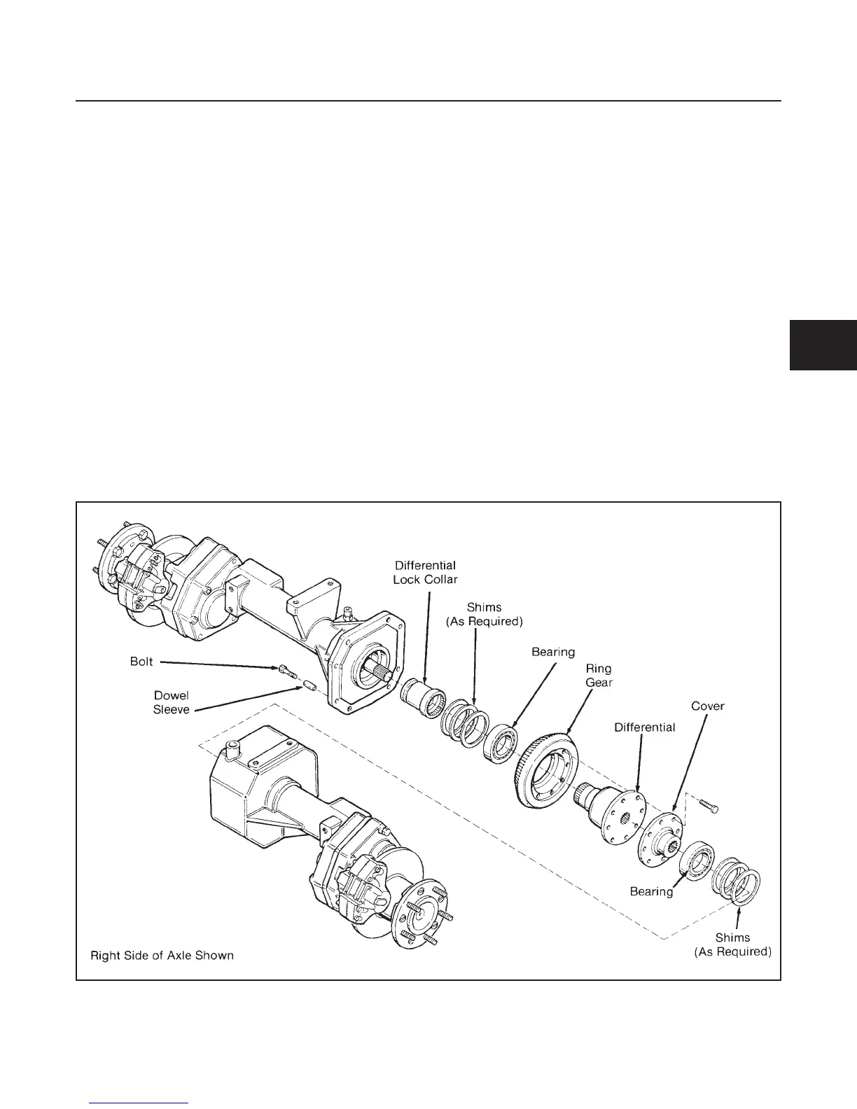
DIFFERENTIAL
GENERAL
Separate the axle housing only if bearings, pinion
gear, ring gear, differential lock collar, and/or differen-
tial are worn or damaged.
If the differential and/or bearings are replaced, see Pin-
ion and Ring Gear Backlash Adjustment in this section.
Separate the axle housing only if bearings, pinion gear,
ring gear, differential lock collar, and/or differential are
worn or damaged.
If the differential and/or bearings are replaced, see Pin-
ion and Ring Gear Backlash Adjustment in this section.
If the ring gear or differential lock collar are to be re-
placed, reinstall the original shim packs removed at
disassembly.
REPAIR
Refer to Figure 4E-8 for disassembly and Figure 4E-9
for reassembly procedures. Be sure to follow all the
steps and special notes.
DRIVE TRAIN
SECTION 4E. AXLE
4E-7
4E
Figure 4E-8. Differential Disassembly