DISASSEMBLY (See Figure 4E-3)
NOTE
Before removing the input bevel pinion assembly
from the axle, complete Step 1.
1. Remove the elastic nut.
NOTE
Once the elastic stop nut is loosened a new col-
lapsible spacer must be installed.
2. Remove input bevel pinion assembly from axle.
3. If the original pinion shaft is to be used, remove
the shim pack, tag and mark it for reassembly. If
the shims are damaged, replace them with shims
equal to the thickness of the shims removed.
4. Support the pinion housing and bearing, press pin-
ion shaft from bearings.
5. Remove spacer, seal, taper bearings and collap-
sible spacer.
DRIVE TRAIN
SECTION 4E. AXLE
4E-3
4E
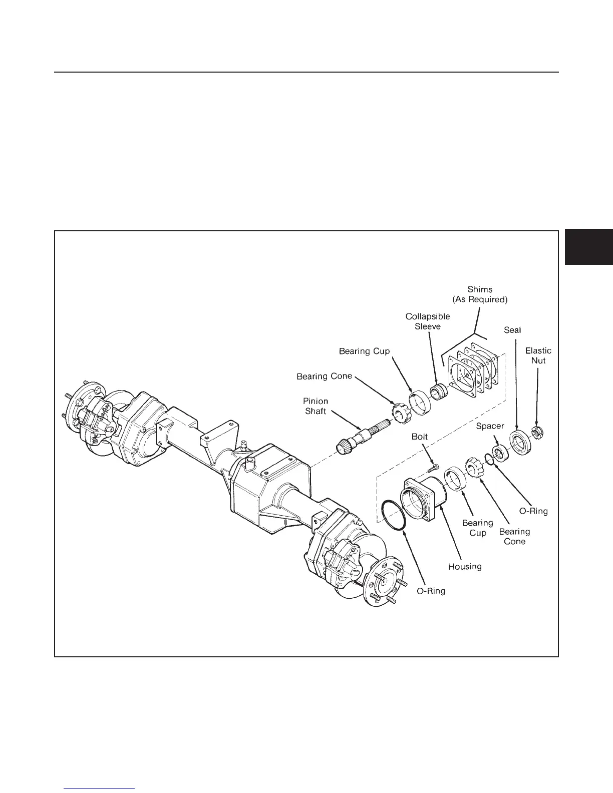
Figure 4E-3. Input Bevel Pinion Disassembly
 Loading...


