This section is divided into four subsections; Differ-
ential Lock Assembly, Input Bevel Pinion, Reduction
Gear and Drive Axle and Differential.
For information on brake repair, refer to Sections 5D
and 5E.
In most cases the entire axle assembly will not be disas-
sembled. Refer only to the section the failure occurred.
If it becomes necessary to disassemble the entire axle,
follow the steps in each subsection.
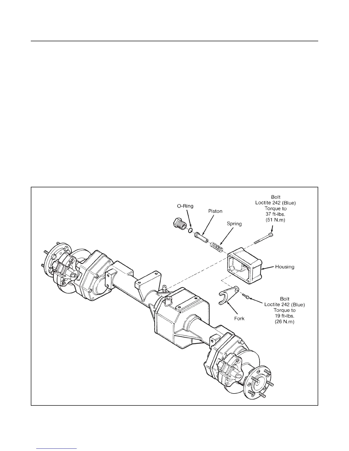
DIFFERENTIAL LOCK ASSEMBLY
(See Figure 4E-2)
Repairs to the differential lock assembly is limited to
renewing worn or broken parts.
To repair the sliding differential lock collar, refer to
Differential, Disassembly for removal and Reassembly
for installation.
INPUT BEVEL PINION
GENERAL
The input bevel pinion and ring gear are a matched
set and should be replaced as a set.
Replace all O-rings with new ones.
If the input bevel pinion is to be serviced and the original
pinion shaft and ring gear used, proceed with Steps 1
through 5.
If the input bevel pinion and ring gear are to be re-
placed, proceed as follows:
For the input bevel pinion, perform Steps 1, 2, 4 and
5, omitting Step 3.
For the ring gear, subsection Differential Disassembly,
Reassembly and Pinion Gear Backlash Adjustment.
DRIVE TRAIN
SECTION 4E. AXLE
4E-2
Figure 4E-2. Differential Lock Assembly