BLADE SPINDLE ASSEMBLY
GENERAL
There are 7 motors, one for each blade on the HR111.
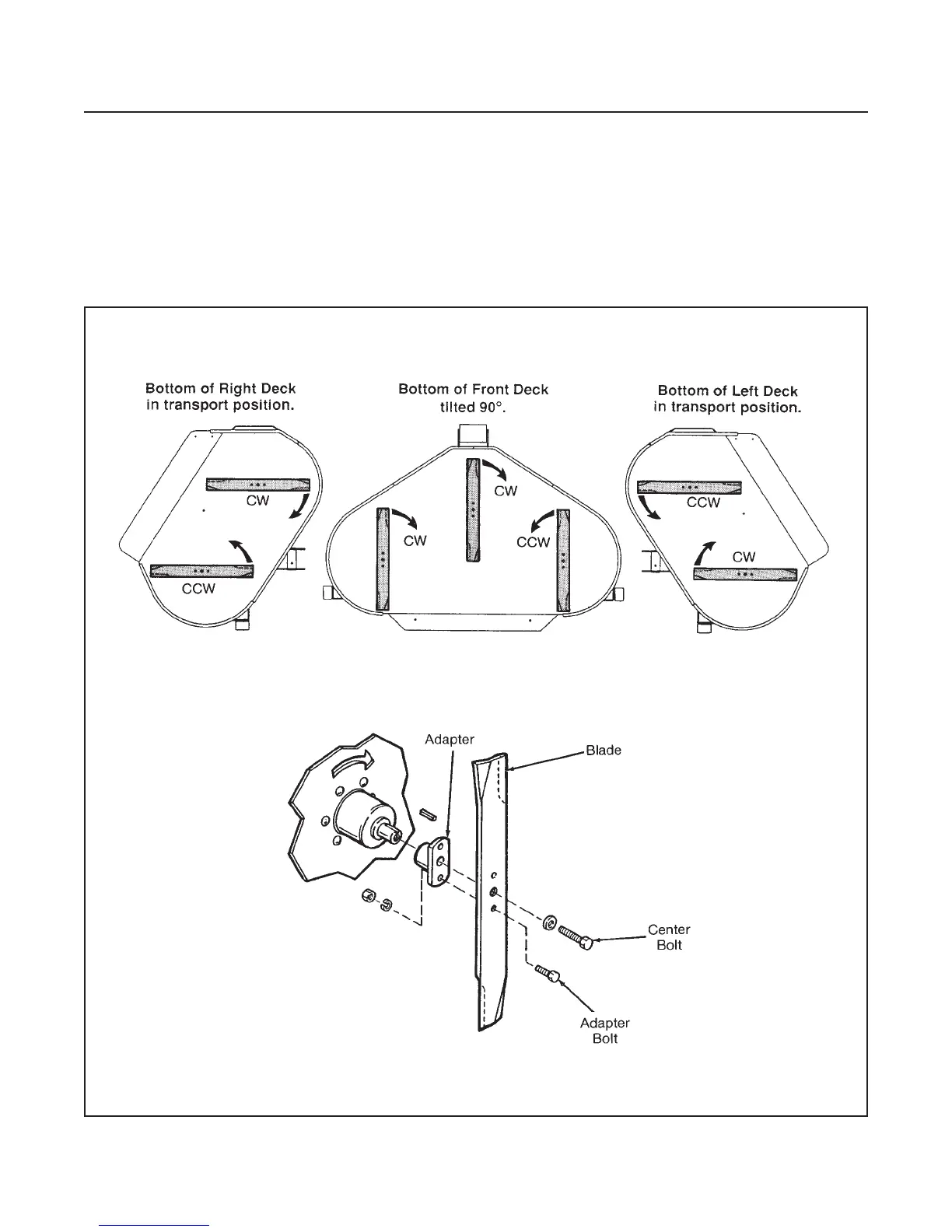
Motor rotation is identified in two ways, first: by their
position on the decks, see Figure 12D-4 and second:
by the code letter which is part of the model number,
see Figure 12D-5.
In this section service of the motors consists only of
the spindle assembly. For service of the hydraulic mo-
tor see Section 8O.
In most cases the spindle housing and motor do not
have to be removed to service the spindle assembly.
If the spindle bearing in the housing needs to be re-
placed it will be necessary to only remove the hydrau-
lic motor.
ATTACHMENTS
SECTION 12D. MOWERS
12D-4
Figure 12D-4. Motor Locations On Decks