PINION AND RING GEAR BACKLASH
ADJUSTMENT
General
There are two methods described to adjust backlash.
Method “A” and “B” should be reviewed prior to per-
forming the adjustment to determine which will be used.
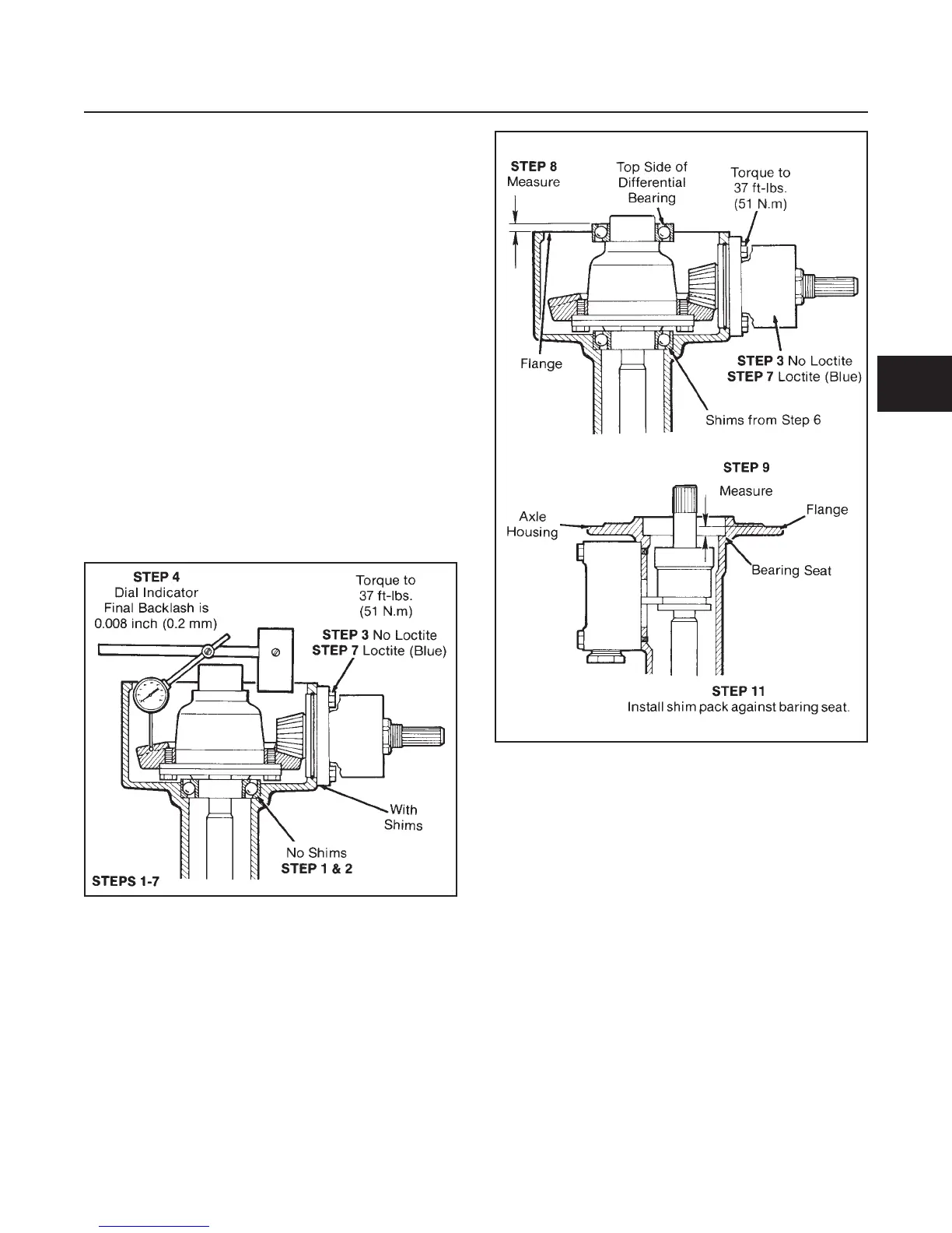
Method “A” (See Figure 4E-11)
1. Press bearings onto the differential assembly.
2. Install the differential assembly with no shims into
the gear case. Make sure bearing is seated in the
bearing bore.
3. Install input bevel pinion with shim pack and torque
to 37 ft-lbs. (51 N.m).
4. Using a dial indicator against a pinion tooth, check
the gear backlash.
5. Subtract backlash of 0.008" (0.2 mm) from the mea-
surement obtained. Build a shim pack equal to the
final dimension.
6. Remove the differential assembly, place the shim
pack in the bearing bore of the gear case.
(See Figure 4E-12)
7. Install differential and input bevel pinion. Apply
Loctite
®
242 (Blue) to the pinion housing bolts and
torque them to 37 ft-lbs. (51 N.m).
8. Measure the distance from the side of the differ-
ential bearing to the gear case flange surface.
9. In the axle housing, measure the distance from
the flange to the bottom of the bearing seat.
10. Subtract the two measurements. From the answer
add 0.004" (0.1 mm). This is the thickness of the
shim pack.
11. Build a shim pack equal to the thickness obtained
in Step 10 and install it against the bearing seat of
the axle housing.
12. Continue to assemble axle as in Figure 4E-9.
Method “B” (See Figure 4E-11)
1. Press bearings onto the differential assembly.
2. Install the differential assembly with no shims into
the gear case. Make sure bearing is seated in the
bearing bore.
3. Install input bevel pinion with shim pack and torque
to 37 ft-lbs. (51 N.m).
DRIVE TRAIN
SECTION 4E. AXLE
4E-9
4E
Figure 4E-11. Pinion and Ring Gear
Backlash Adjustment
Figure 4E-12. Pinion and Ring Gear
Backlash Adjustment