4. Using a dial indicator against a pinion tooth, check
the gear backlash.
5. Subtract backlash of 0.008" (0.2 mm) from the
measurement obtained. Build a shim pack equal
to the final dimension.
6. Remove the differential assembly, place the shim
pack in the bearing bore of the gear case.
7. Install differential and input bevel pinion. Apply
Loctite
®
242 (Blue) to the pinion housing bolts and
torque them to 37 ft-lbs. (51 N.m).
(See Figure 4E-13)
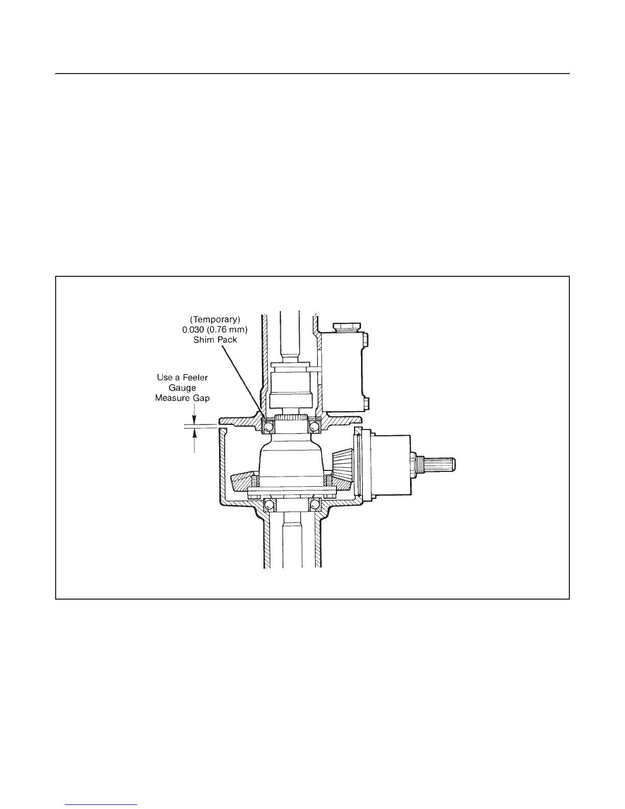
8. Build a shim pack equal to 0.030" (0.76 mm) and
install it in the bearing bore of the right axle.
9. Assemble both axle halves together.
10. Snug the bolts evenly, do not tighten.
11. Using a feeler gauge, measure the gap between
the two axle halves.
12. To this dimension subtract 0.004" (0.1 mm), then
subtract the total from the 0.030" (0.76 mm). This
is the thickness of the shim pack needed.
13. Separate the axle housing halves.
14. Replace the 0.030" (0.76 mm) shim pack with the
correct shim pack.
15. Continue to assemble axle as in Figure 4E-9.
DRIVE TRAIN
SECTION 4E. AXLE
4E-10
Figure 4E-13. Pinion and Ring Gear Backlash
Adjustment (Optional Method)
 Loading...


