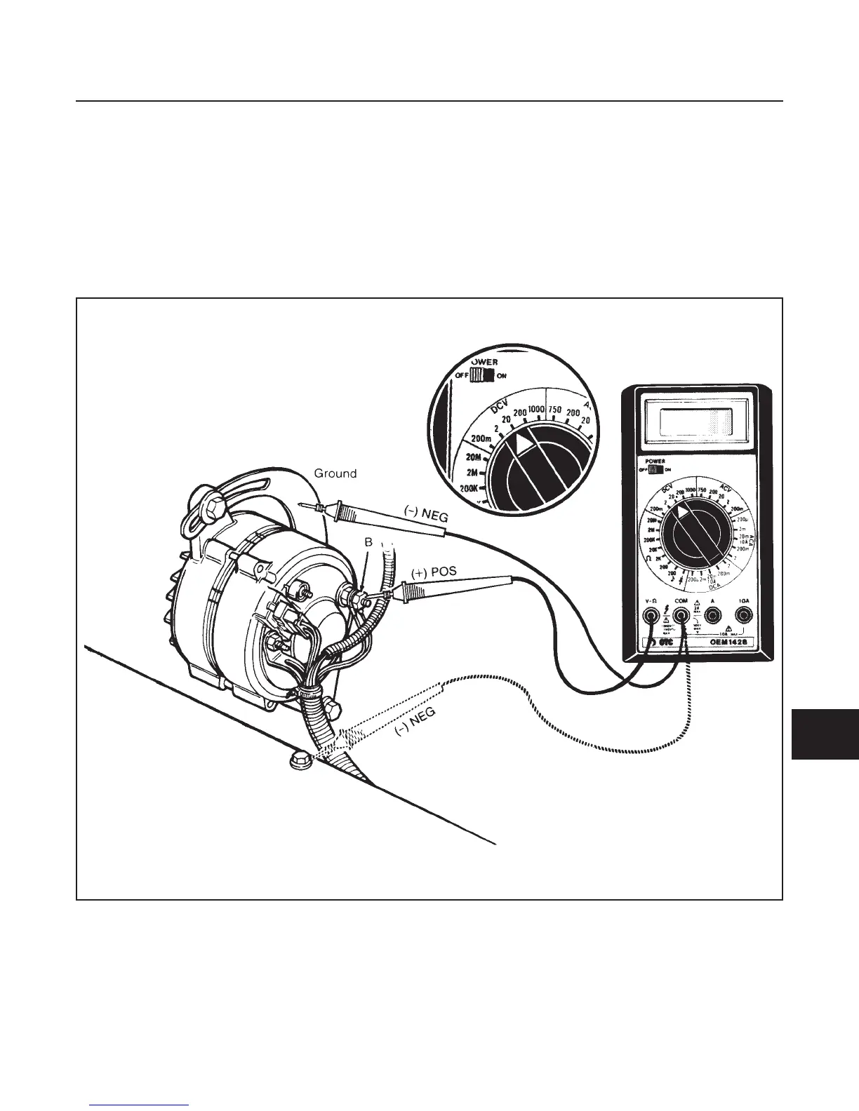
NO LOAD REGULATING VOLTAGE TEST
(See Figure 10E-5)
1. Set the multimeter to the 20 VDC range.
2. Connect the multimeter POS (+) lead to the B ter-
minal and the NEG (–) lead to the ground.
3. Start and run the engine at idle.
4. Remove the NEG (–) battery cable.
5. Gradually accelerate the engine and watch the
multimeter.
•
Voltage should rise as engine rpm increases.
Voltage should read 13.8 to 14.8 VDC.
•
If voltage does not increase with increased eng-
ine rpm, proceed with regulator test.
•
If regulator tests okay, alternator may need to
be repaired.
ELECTRICAL SYSTEM
SECTION 10E. CHARGING SYSTEM
10E-5
10E
Figure 10E-5. No-Load Regulating Voltage Test
 Loading...


