DIFFERENTIAL LOCK
4 WHEEL DRIVE (See Figure 10I-3)
1. Energize the solenoid.
2. Notice if the LED (light emitting diode) is lit.
•
If LED is lit, proceed with Step 3.
•
If LED does not light, check interlock switches
and wiring.
3. Remove the Hirshman connector from solenoid.
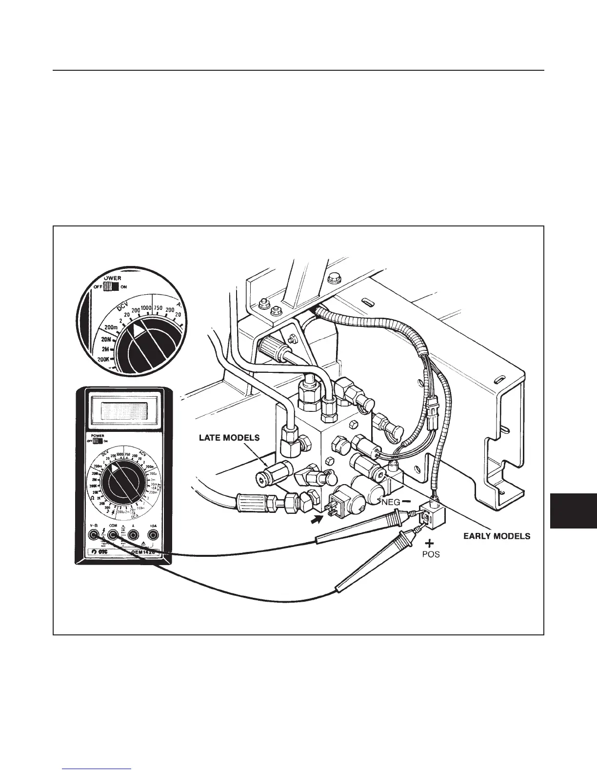
4. Set multimeter to 20 VDC range.
5. Connect black NEG (–) multimeter lead to con-
nector as shown.
6. Connect red POS (+) lead of multimeter to con-
nector as shown.
•
Multimeter reads battery voltage, coil may be
faulty, proceed with Step 7.
•
Low or no voltage, check for high resistance or
opens in wiring and/or interlock switch.
ELECTRICAL SYSTEM
SECTION 10I. SOLENOIDS
10I-3
10I
Figure 10I-3. Solenoid Plug Test
 Loading...


