EasyManuals Logo

Jacobsen HR5111 User Manual

Jacobsen HR5111
339 pages
To Next Page IconTo Next Page
To Previous Page IconTo Previous Page
Page #270 background imageLoading...
Page #270 background image
CRUISE DISENGAGE (BRAKE RELAY)
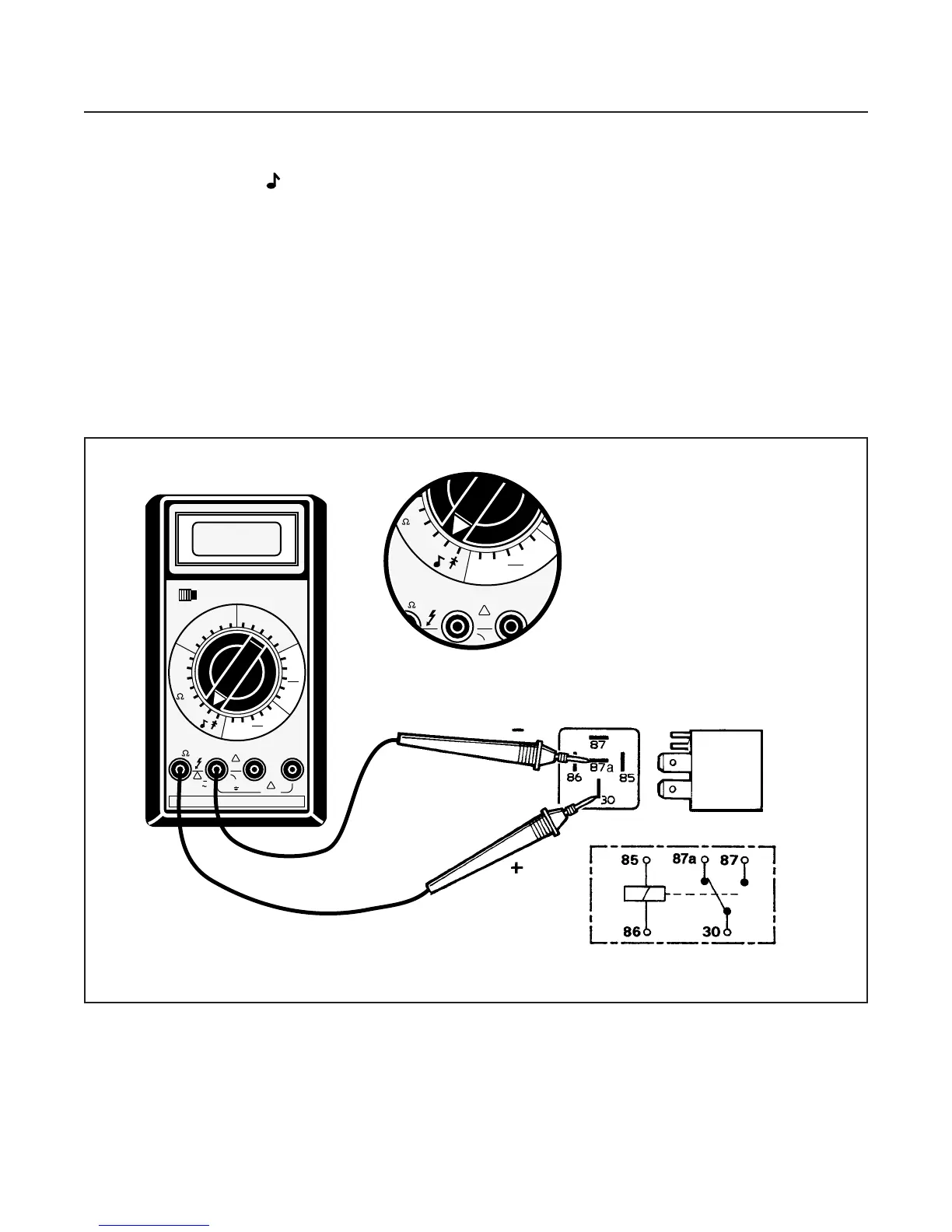
(See Figure 10H-2)
1. Set multimeter to 200 (ohms) scale.
2. Connect black NEG (–) lead from multimeter to
terminal 30.
3. Connect red POS (+) lead from multimeter to ter-
minal 87a.
There should be continuity. If there is no conti-
nuity, replace relay.
4. Move the red lead to terminal 87.
There should be no reading on multimeter (no
continuity). If there is a reading, replace relay.
5. Connect 12V across terminals 85 and 86. There
should be an audible “click”.
6. Connect black NEG (–) lead from multimeter to
terminal 30.
7. Connect red POS (+) lead from multimeter to ter-
minal 87a.
Open when coil is energized.
8. Move red lead to terminal 87.
Closed when coil is energized.
ELECTRICAL SYSTEM
SECTION 10H. RELAY
10H-2
POWER
OFF ON
200m
2
20
200
1000
750
200
20
2
200m
20M
2M
200M
20K
2K
200
200
DCV
ACV
ACA
200µ
2m
200m
2
2
200m
20m
10A
2m
200µ
DCA
20m
10A
COM A 10A
!
1000V
750V
MAX
!
!
2A
MAX
10A MAX
500V
MAX
200m 200m
20M
2M
200M
20K
2K
200
200
ACA
200µ
2m
200m
2
2
200m
20m
10A
2m
200µ
DCA
20m
10A
COM A
!
2A
MAX
-
V -
Figure 10H-2. Brake Relay Test

Table of Contents

Questions and Answers:

Question and Answer IconNeed help?

Do you have a question about the Jacobsen HR5111 and is the answer not in the manual?

Jacobsen HR5111 Specifications

General IconGeneral
BrandJacobsen
ModelHR5111
CategoryLawn Mower
LanguageEnglish

Related product manuals